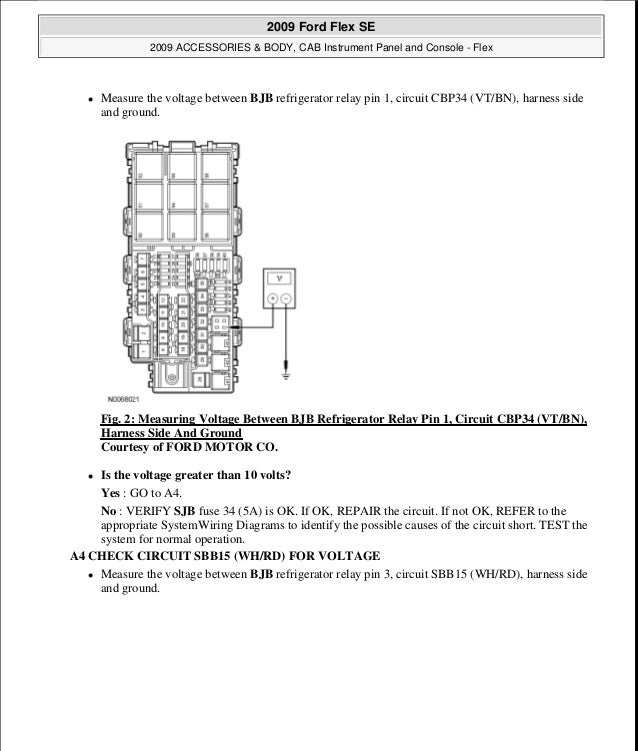
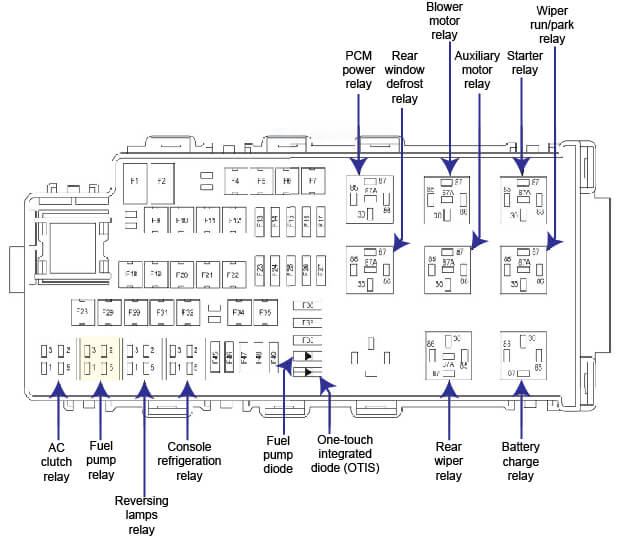
Official manual of the dealerships. 2013 ford flex electrical wiring diagrams.

Td 4953 Envistar Flex Wiring Diagrams Wiring Diagrams And
Flex 7 wiring diagram. In line terminals a snap onsnap off cover and a pair of screws. An incorrectly applied or installed drive can result in component damage or a reduction in product life. This is the real thing written by the manufacturer specifically for the vehicles listed. Wiring or application errors such as. Allen bradley powerflex 70 fault codes and descriptions. This ensures you get the job done right the first time.
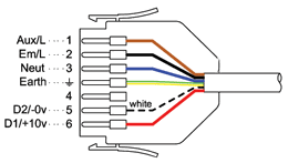
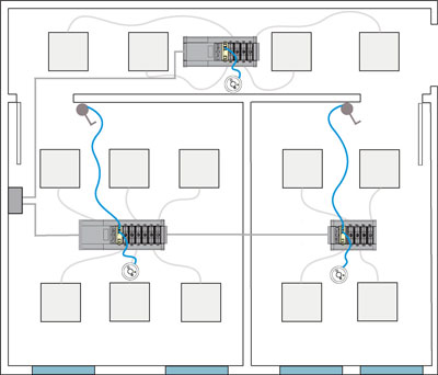
3 4 5 6 7 pin plugs available in white red or black flex7 plugs are robust and simple to use. Klik provides the roots for a buildings lighting system allowing it to adapt and grow with ease. The flex7 lighting connection and control system is designed and manufactured in the uk. How the flex7 sy st em works. 028 28 75 10 d 042 42 11 15 054 54 15 20 e 070 70 185 25 internal brake resistor code w resistor yyes nno comm slot code network type c controlnet coax d devicenet e ethernetip n none powerflex 70 nd rating 400v 50 hz input code amps kw hp frame 1p3 13 037 05 2p1 21 075 10 a 3p5 35 15 20 5p0 50 22 30 b 8p7 87 40 50 011 11. 6 rockwell automation publication 20b in014h en p june 2013 powerflex 700 adjustable frequency ac drive frames 710 product safety attention.
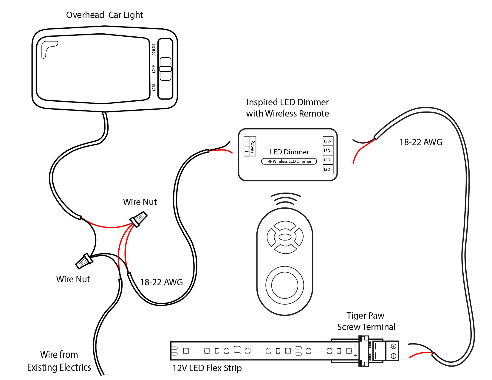
Check the motor and external wiring to the drive output terminals for a grounded. We provide modular lighting connection and control solutions for industrial and commercial buildings. John w5gi flexradio systems engineering for those of you who have hum problems with your heil goldline microphone please note the correct wiring is as follows. 1995 chevrolet silverado wiring diagram 1995 chevy silverado 1500 wiring diagram 1995 chevy silverado 57 wiring diagram 1995 chevy silverado ac wiring diagram 1995 chevy silverado alternator wiring diagram 1995 chevy silverado radio wiring diagram 1995 chevy silverado starter wiring diagram 1995 chevy silverado trailer wiring. The system simply plugs together on site resulting in greatly reduced installation time and less requirement for skilled labour. Wiring diagrams dimmer with multiple light fixtures fluence dc flex dimming wiring system components 1 dimmer c w u 2 dimming signal wire connector adma 70983 10 2a signal wire set screws 3 120 vac power adapter adma 10342 10 4 dc flex pigtail trunk extension cable 5 ft cdma 71389 10 or 75 ft cdma 71366 01 5 dc flex t connector cable to.
The below wiring scheme results in no hum. All models trim styles including se sel limited fwd awd 35l v6 engine. Controls including occupancy sensors ensure that light is only available when needed and tailored to a users needs. Powerflex 70 drives are designed to worldwide standards providing out of the wiring and grounding guidelines for pulse width modulated pwm ac drives. This is for the mic that has the four pin xlr male connector in the mic.
