All types of capacitor used for ac chiller freezer water pump fan motor duration. Wall fans extend the proper gauge wire to the fan motor.

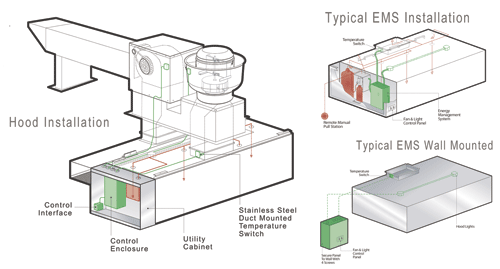
Greasemaster Manufacturers Of Kitchen Ventilation Systems
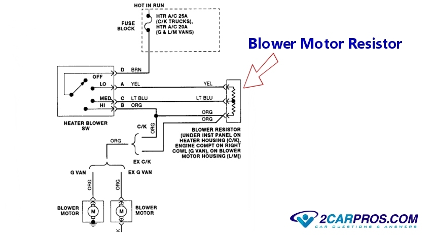
Exhaust fan motor wiring diagram. It shows the components of the circuit as simplified shapes as well as the power as well as signal connections in between the gadgets. Installing and wiring a bath exhaust fan and light electrical question. Tutorial light wiring with switch. Double check your connections using the fan wiring diagrams. You should see that there is a separate motor winding for high speed. How to verify fan motor wiring connections.
3ø wiring diagrams 1ø wiring diagrams diagram er9 m 3 1 5 9 3 7 11 low speed high speed u1 v1 w1 w2 u2 v2 tk tk thermal overloads two speed stardelta motor switch m 3 0 10v 20v 415v ac 4 20ma outp uts diagram ic2 m 1 240v ac 0 10v outp ut diagram ic3 m 1 0 10v 4 20ma 240v ac outp uts these diagrams are current at the time of publication. Checking the motor and capacitor connections. Follow the wiring diagrams on the motor nameplate. To correct rotation of fans reverse any two leads from the 3 phase starter to the fan. How to connect fan coil easy 5 wire ac fan motor wiring diagram 3 speed duration. So im thinking that the motor may have to start with the slower.
Afcs wiring diagram list the proper phase voltage and amp load. A wiring diagram is a simplified conventional pictorial representation of an electric circuit. Canarm exhaust fan wiring diagram gallery. Have to be removed in order to make the connections in the motor terminal box. Exhaust hood motor schematic diagram scj tech vlog. Table fan motor repair exhaust fan motor repair.
Wall fans with cabinets remove guard from cabinet. The concern is that there is a capacitor for the motor. Variety of canarm exhaust fan wiring diagram. 3 speed electric fan motor wiring diagram. Verify input power voltage before connecting to starters or contactors. Check rotation of fans exhaust fans will move some air in reverse see rotation arrow on fan.
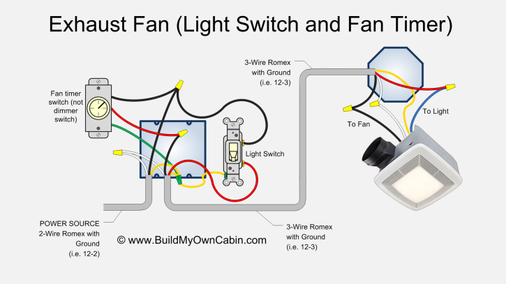
After my bathroom addition was rough wired and before the insulation was done i decided to add a ceiling fan and light to be controlled with separate switches in place of a simple light fixture. Removing existing wiring i removed the 2 wire with ground from the switch to fixture and replaced it with a 3 wire with a ground. From what you are describing you have taken apart the wiring that most likely involves the switch controls for the exhaust fan and the light so you will need to identify the wiring to the switch for the light and the switch for the fan in order to make the correct connections for the fan and light. Restrain excess wire from entering the shaft and propeller area.


