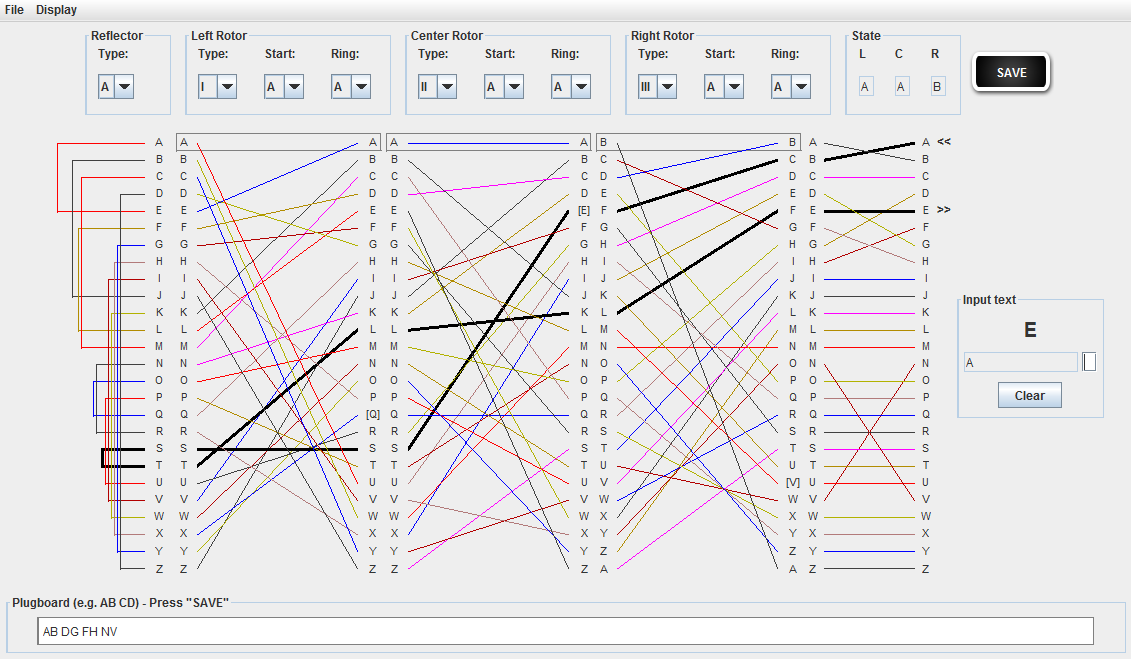
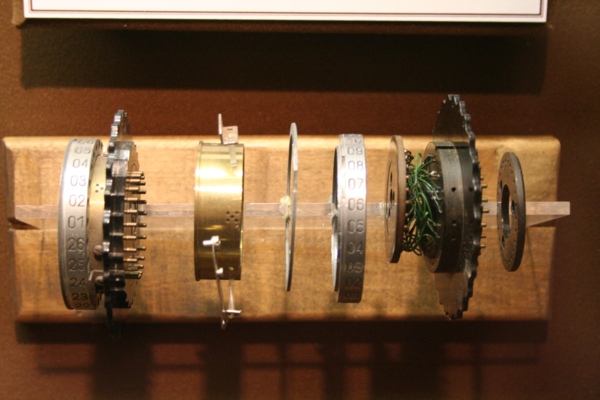
All wiring measurements are made per convention with ringstellung a. Each rotor has 26 spring loaded terminals on its right side and 26 flat circular terminals on its left side.

Make Your Own Enigma Replica 11 Steps With Pictures
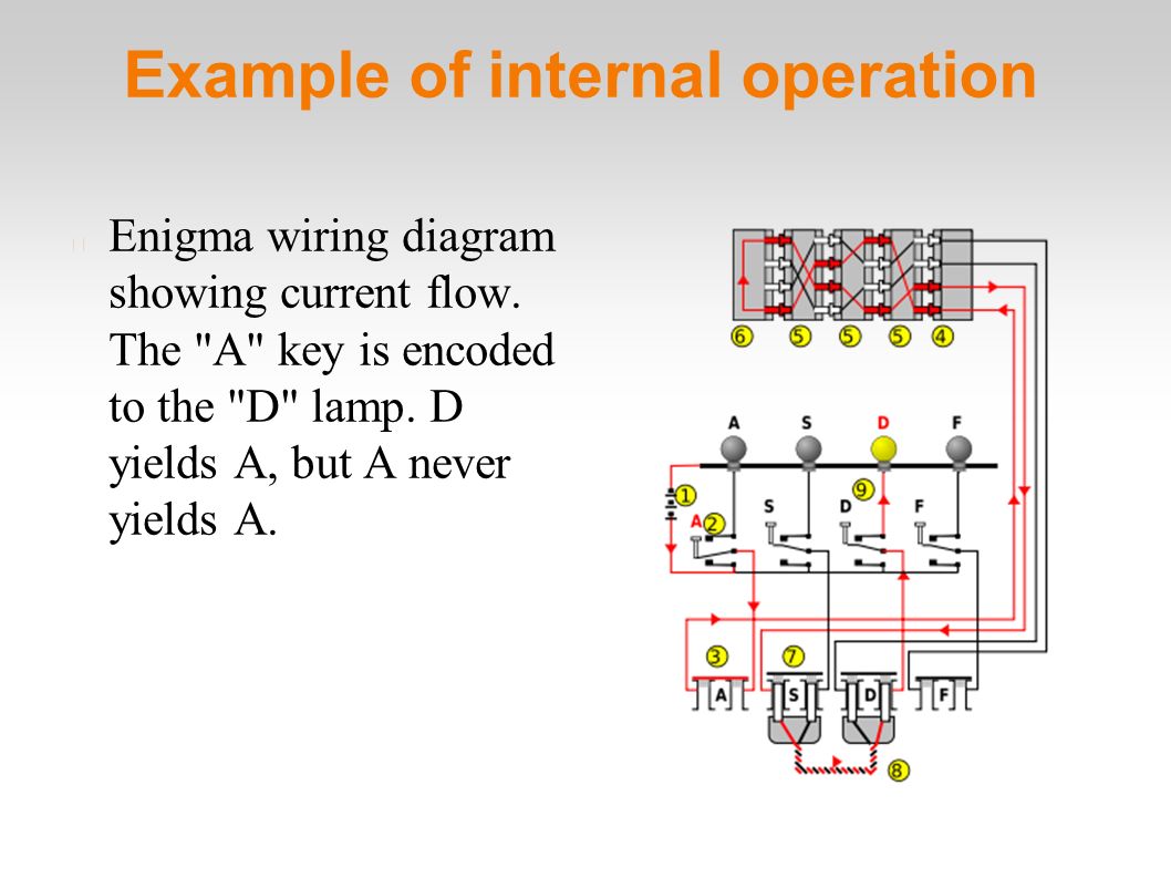
Enigma wiring diagram. On 1 february 1942 the enigma messages began to be encoded using a new enigma version that had been brought into use. Simplified circuit diagram of a 3 wheel service enigma letters are scrambled by a set of rotatable wheels each with 26 contacts on either side. To explain the enigma we use this wiring diagram. Enigma is intended to be an open extensible system. Each rotor has different fixed internal random fashioned wiring from the left side to the right side of the wheel. An abwehr enigma cryptologia january 2000 volume xxiv number 1.
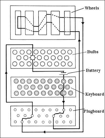
Enigma machine wiring diagram. This example is of a swiss air force enigma. Recovering the wiring of enigmas umkehrwalze a cryptologia january 2000 volume xxiv number 1 pp. Trace the battery voltage through the keyboard letter q the plugboard the rotors the plugboard again the keyboard again and ultimately to the light bulb letter w. Each contact on one side is connected wired to a contact on the other side in some random fashion. It consists of a keyboard german qwertz layout a lamp panel representing the alphabet and three or four rotors.
The previous 3 rotor enigma model had been modified with the old reflector replaced by a thin rotor and a new thin reflector. Us military attaché in argentine intelligence report about g 260. David hamer and frode weierud wiring of norway enigma personal correspondence 2001. Two views of the wiring of an enigma rotor. Wiring diagram the enigma machine is an electro mechanical device. The swiss frequently rewired their enigmas and also modified the stepping of the army machines.
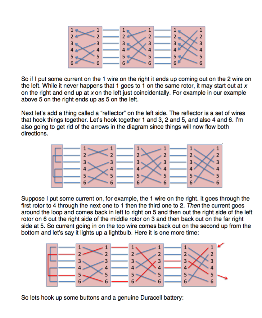
Breaking shark on 3 rotor bombes would have taken 50 to 100 times as long as an average air force or. The heart of the enigma is the rotor wiring. In reality there are 26 lamps keys plugs and wirings inside the rotors. Alphabets progress clockwise when viewed through the eintrittwalze along the wheel axis. For this we study the circuit diagram of a standard 3 wheel wehrmacht enigma. This diagram has the same wiring as indicated by the connection between a on the right and e on the left.
To simplify the example only four components of each are shown. The current flows from the battery 1 through the depressed bi directional letter switch 2 to the plugboard 3. The terminals are arranged in circular mode. Traditionally an efis manufacturer would develop a system and then closely guard all data formats encrypted if required. One or more rotors move on each key stroke. When you look at this unrolled view you have to keep in mind that the top and bottom of the rectangle are in fact connected together to form a circle.
This starts at mundane things such as data formats used for waypoints airfield information maps airspace data and so on.


