Cisa accepts no responsibility for any damages caused by inobservance of the above instructions. System wiring diagrams 1995 chevrolet tahoe 1995 system wiring diagrams chevrolet tahoe air conditioning ac circuit.

1000 Series Exit Devices Ansi Grade 1 Klacci
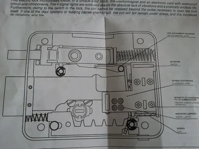
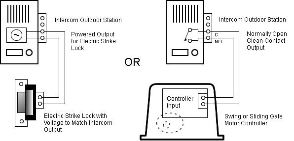
Electric rim lock wiring diagram. 36v 800w set electric bike controller twist throttle brake lever. Clock cig lighter page a 5 6. Riser drawings for auto operators. Wire per diagram on next page. Door locks page a 4 5. See wiring diagram on page 2.
Heater circuit anti lock brakes. 2018 24v36v48v 250w350w bldc motor speed controller 6 mosfet dual. Depress brake pedal and hold depress control switch and hold release brake pedal. The need to reduce vehicle weight has prompted these more complex module driven door lock circuits. Electric door strike wiring diagram. E bike controller wiring diagram recent wiring diagram electric bike.
This wiring diagram uses a sentry fob receiver timer circuit power supply and the av2e winkhaus electric multipoint door lock read more locksonline wiring diagram 007. Wiring diagram for mag lock. 57l 57l vin k cruise control circuit 65l. 6818 s 220th st kent wa 98032 253. The locks are supplied with key. E bike controller wiring diagram collections of e bike controller wiring diagram list diagram electric bike.
Advanced power door lock management is a necessity now given todays complex automotive systems. All wiring connections should be soldered and covered with shrink sleeving. Understanding toyota wiring diagrams. Electric door strike wiring diagram. Shift lock page a 8. Quote request form.
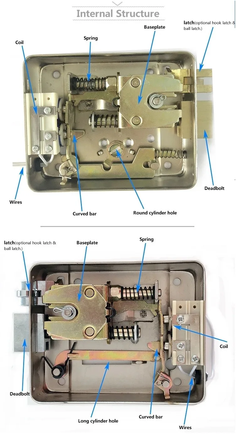
Anti lock brake circuits computer data lines. Front wiper washer page a 6 7. Common wiring diagrams. The units drive a deadbolt into an observed keep to give high security locking. Fast trac form. Directions for installation of rim electric locks instructions for cisa electric rim lock series 11521 11540 1155111560 11610 11560 11610 11611 11630.
Fan blower page a 7 8. Reconnect battery and test for correct operation. Commax double door wiring diagram. 6 716 163mm 7 12 190mm 2470 1 12 38mm rofu installation instructions rofu 2470 electric rim strike 8 203mm horizontal adjustment mounting hole a inside of strike keeper a lock down hole 3 5 4 2 1 rofu security international corp. Data link connector circuit cooling fan. Understanding toyota wiring diagrams information 1 reading toyota electrical wiring diagrams u 1 page 2.
Common wiring d. Electric rim locks are perfect for walker entryways inside and outer entryways. Use standard approved wiring with a minimum cross section of 1 mm. Toyota understanding wiring diagrams worksheets u 1 page 1. Brakes are now locked. Cooling fan circuit cruise control.
