Collection of automotive voltage regulator wiring diagram. Dvr2 d regulator cut out for dynastart field to live type a with 8 amp current limit introduction the dvr2 d formerly dvr2 s is a high quality solid state electronic dynamo regulator for siba bosch dynastarts.
Vintage Veloce Notes On Installing A Dvr2 On A Mondial 175tv
Dvr2 regulator wiring diagram. Ok must be the regulator then. To the rescue ed gilkison popped a dynamo regulators dvr2 into the mail last week. The dvr2 is primarily suited to classic motorcycle fitment and some other lower output dynamo applications. If you connect the white to the units brown wire the dvr2 runs as a 6 volt system. The module is compact and does not run hot. Some of the key benefits of fitting a dvr2 d to the classic vehicle user are in no particular order.
This means it can. The dvr2 can be run either as a 6 volt system or a 12 volt system by either using or omitting a white wire. Failure to do so may result in overcharging and possible. Wire 12 v by leaving it unconnected insulated. Ensure that the field wire of the dynamo goes to the f terminal of the dvr2 and that no other wire is connected. Disconnect or remove any field resistor which may be fitted at the dynamo or elsewhere wire wound item connected to field terminal.
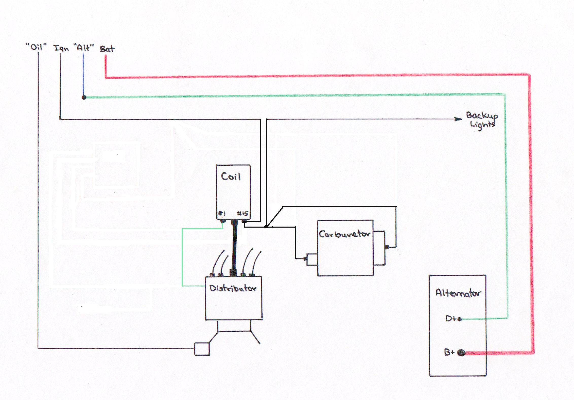
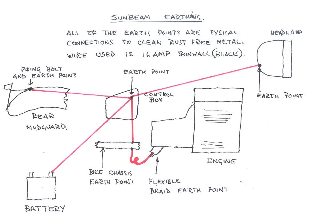
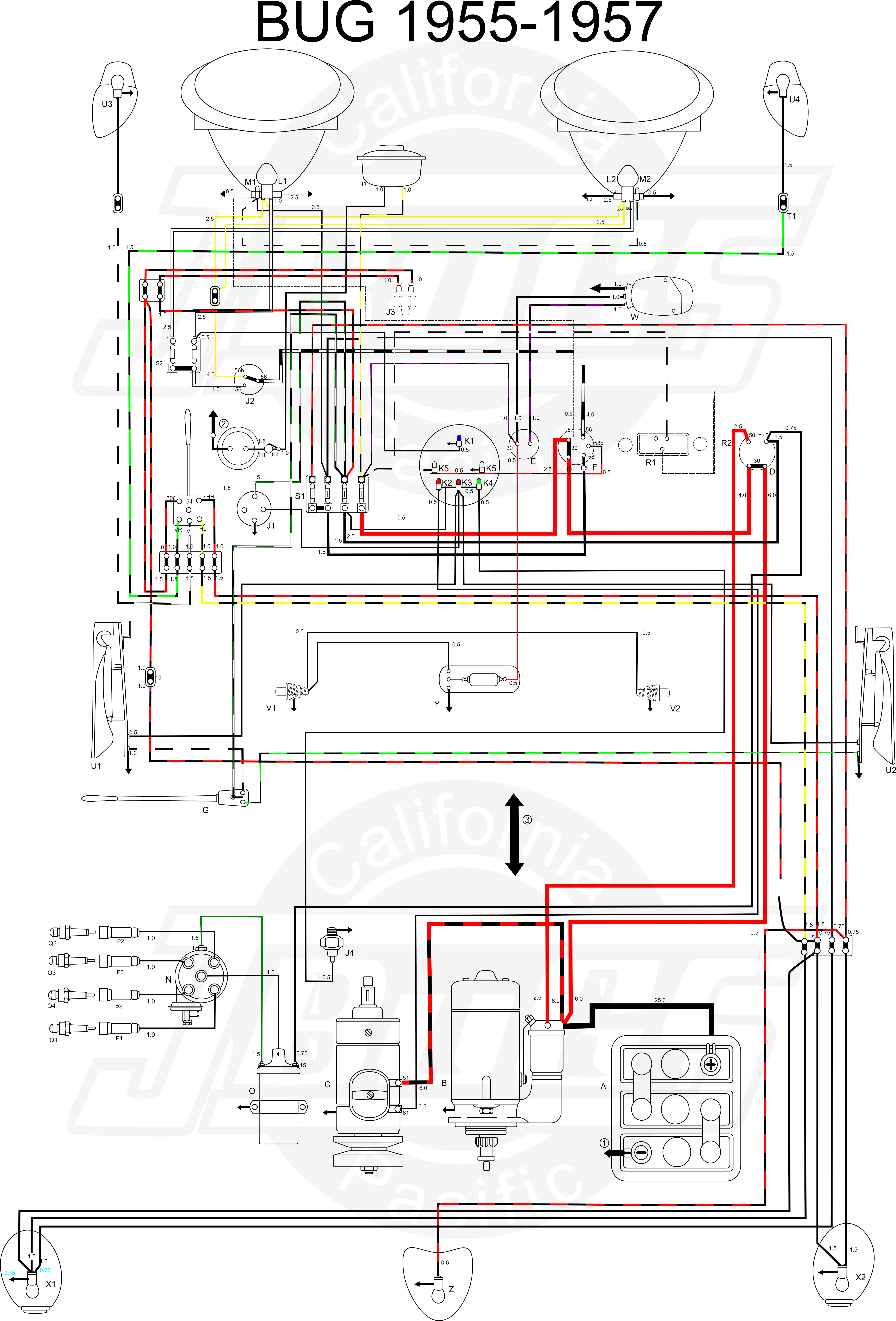
The dvr2 regulator is the well known and well regarded solid state dynamo voltage regulator from dynamo regulators ltd. With the new and old regulators bolted back to the bike the wiring connections could then be made. Real risk of damaging the regulator. It reveals the components of the circuit as simplified forms and also the power and also signal links between the tools. A wiring diagram is a streamlined standard photographic representation of an electric circuit. Like the old lucas regulator the dvr2 unit only has four wires remember fade field ammeter dynamo and earth.


