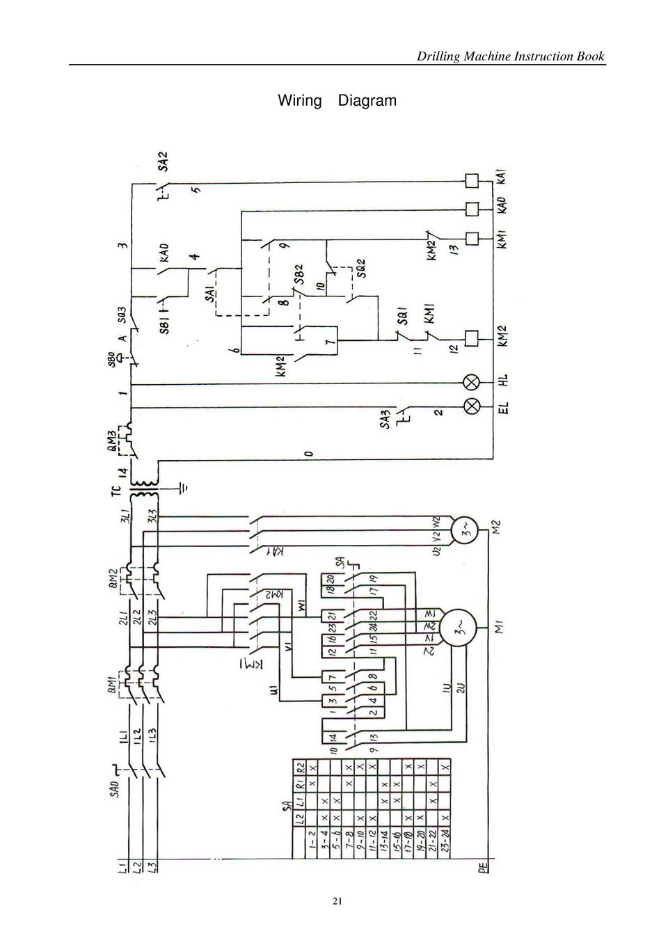
3ø wiring diagrams 1ø wiring diagrams diagram er9 m 3 1 5 9 3 7 11 low speed high speed u1 v1 w1 w2 u2 v2 tk tk thermal overloads two speed stardelta motor switch m 3 0 10v 20v 415v ac 4 20ma outp uts diagram ic2 m 1 240v ac 0 10v outp ut diagram ic3 m 1 0 10v 4 20ma 240v ac outp uts these diagrams are current at the time of publication. Products support innovations power tools mx fuel equipment batteries and chargers site lighting outdoor power equipment instruments hand tools storage jobsite apparel accessories safety solutions one key.

158 Typical Electric Drill Switch Wiring Diagram Wiring Library
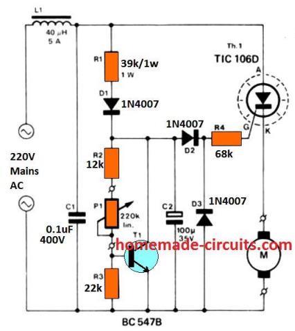
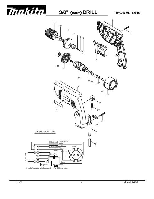
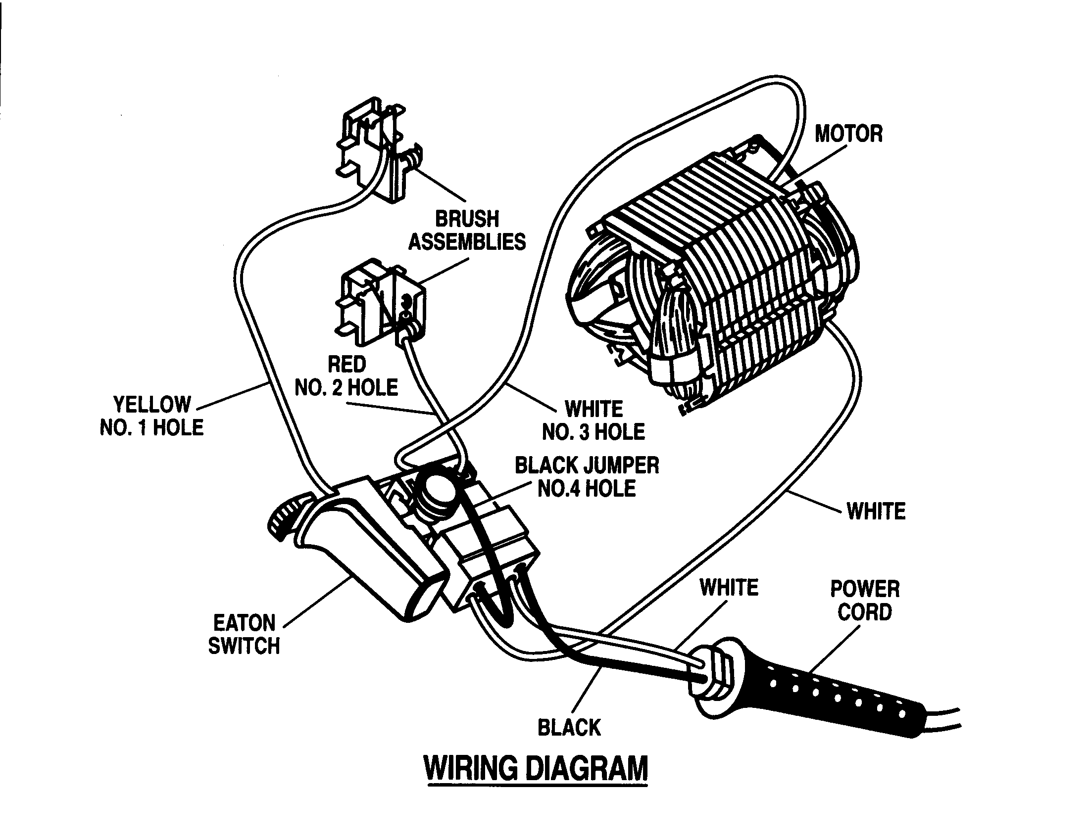
Drill wiring diagram. User manuals black decker drill operating guides and service manuals. Many drills and other tools have screw type connections at the switch. For stabbed in connections you might insert a small diameter sharp instrument next to the wire to depress the locking tag that secures the wire then pull the wire free from the connector. Steel box capacities are listed in the electrical code. Plastic boxes have their volume stamped inside. If in any doubt consult a suitably qualified electrician.
2 for each device switch or outlet but not light fixtures multiply the total by 2 for 14 gauge wire and 225 for 12 gauge wire to get the minimum box size required in cubic inches. A quick video on how to wire an nvr switch no volt release switch with an emergency stop e stop. Download milwaukee tool operators manuals service parts kits and wiring instructions and msds documents. Video intended as a guide only. These are removed by simply loosening the screws and removing the wires. Download 850 black decker drill pdf manuals.


