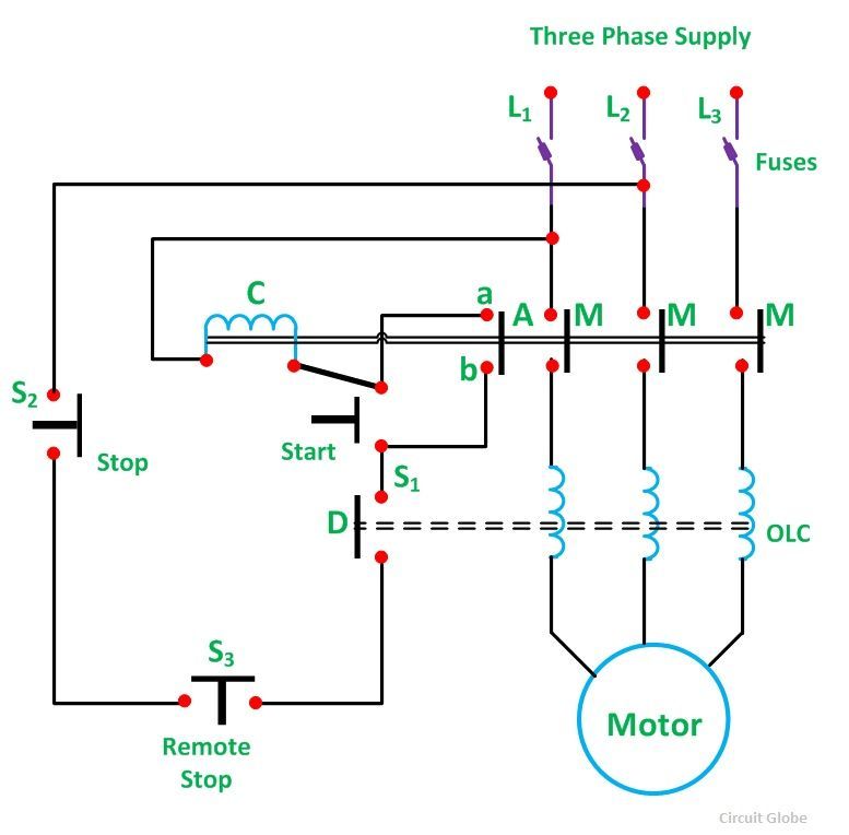
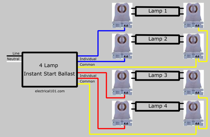
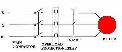
This is why such a starter is used with induction motors rated below 5 hp. Schematic and circuit diagram.
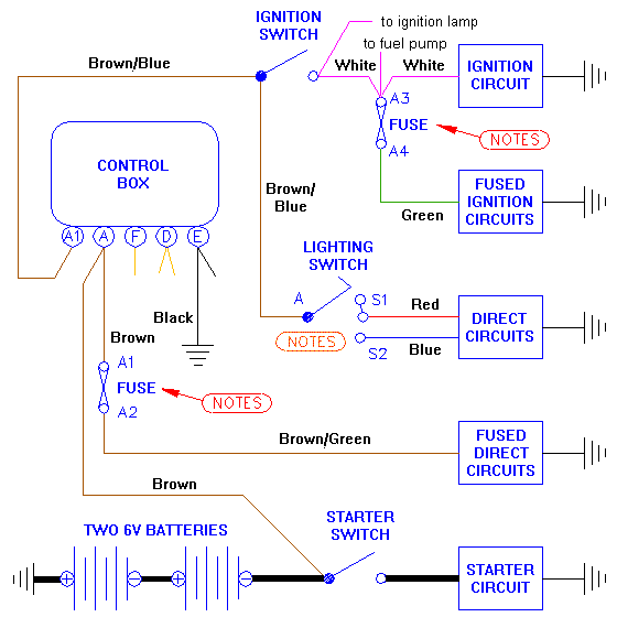
Mga Base Electrical Load Diagram
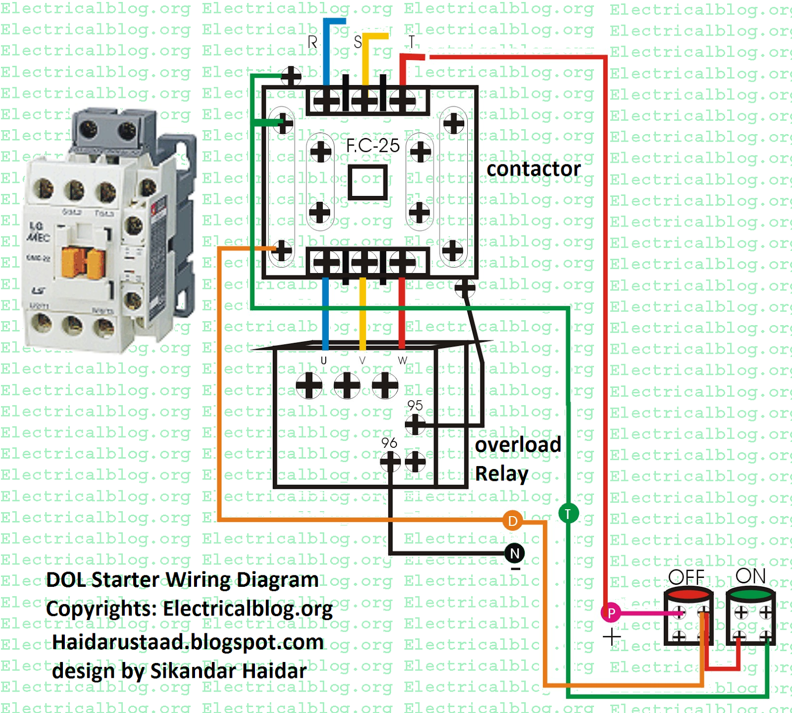
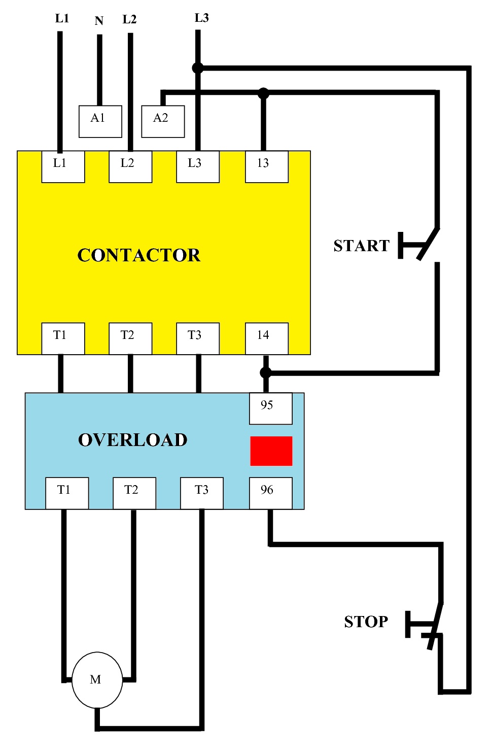
Direct on line wiring diagram. The l1 contactor is connected from normally open no to r phase using mccb. These two buttons ie. The dol starter comprises of an mccb or circuit breaker contactor and an overload relay for protection. The wiring diagram for a dol stater is shown below. A direct online starter consits of two buttons a green button for starting and a red for stopping purpose of the motor. Three phase and single phase.
How to wire auxiliary latching contact on the contactor. Find out how to wire direct on line motor starter add remote start stop push buttons and extra leds. How to wire a contactor and overload. The wiring of direct on line control circuit starter is following. In this article we will discuss dol starter direct online starter working principle and construction dol starter diagram control diagram power circuit and wiring single 3 phase starter direct on line is the simplest and cheapest method used for starting three phase motor. Green and red or start and stop buttons control the contacts.
Dol starter control diagram three phase. Direct on line starter. Three phase motor control and design power circuit and installation. The connection of contactor can be done among relay coil supply voltage as well as thermal overload. The direct online or dol starter employs full voltage or across the line starting technique where the motor is directly connected to full voltage through mccb or circuit breaker and relays for overload protection.
