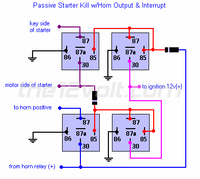
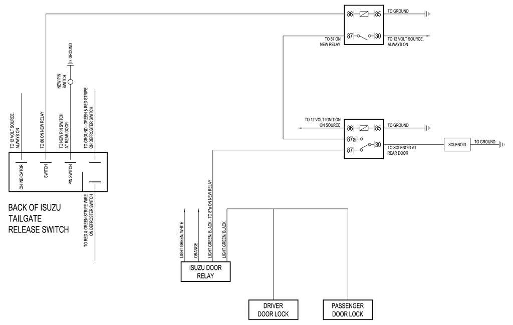
This wire is pre wired to the starter kill relay and must show 12 volts with the key in run position and during cranking. Tem can be used to roll the windows up as shown in the diagram below.

Relay Remote Switch 2ch Dc3 7v 4 2v 5v 6v 7 4v 8 4v 9v 12v
Dei 610t relay wiring diagram. H110 brown siren output connect this to the red wire of the revenger siren. For heavy duty automotive electrical switching. Connect this wire to an optional relay pn 610t to bypass sensors which may trigger the security system during operation. Directed relay assembly discontinued by. The directed electronics 610t directed relay is ideal for heavy duty automotive electrical switching. Directed is the largest designer and marketer of consumer branded car alarms and remote starters in north america.
Directed electronics 610t directed relay by directed electronics. Connect this wire to optional relay pin 610t to bypass sensors which may trig ger the security system during operation. This wire continues to output negative ground for 5. The wiring diagram on the opposite hand is particularly beneficial to an outside electrician. H25 gray output during activation. This wire continues to output ground for 5 seconds after the window motors have stopped.
Wiring diagram book a1 15 b1 b2 16 18 b3 a2 b1 b3 15 supply voltage 16 18 l m h 2 levels b2 l1 f u 1 460 v f u 2 l2 l3 gnd h1 h3 h2 h4 f u 3 x1a f u. Directed electronics 610t relay wiring diagram ground then use a wire jumper to power up the vehicle ignition wire which will power up the pats system. Nilight 50003r automotive set 5 pin 3040a 12v spdt with interlocking relay socket and wiring harness 5 pack2 years warranty 47 out of 5 stars 618. 36 out of 5 stars 2 ratings. Maker of the award winning viper smartstart mobile app. Wiring diagrams are available on the website in order to assist with the wiring of the relays.
It is a 3040a relay. Nissans and some newer chryslers. 799 free. Directed electronics 610t directed relay. From the security system can be used to roll the windows up as shown in the following diagram. H25 gray output during activation.
Take great care that this wire cannot be shorted to the chassis at any point. Please note that some cars have two starter wires ie. Connect the starter wire output from the remote starter unit to this wire. Connect this wire to the 12 volts ignition wire. Overload relay 1ct m m motor 3ct to 120 v separate control ot is a switch that opens when an overtemperature condition exists type mfo and mgo only t1 t3 motor 3 2 l2 t2 l3 t3 t2 l1 1 t1 13. In this case you will need two relays to properly interface both starter wires.
Once kit is programmed connect brown wire.


