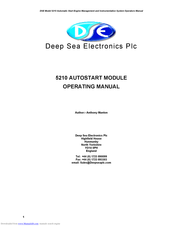
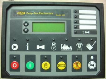
Deep sea electronics plc reserve the right to change specification without notice. Deep sea electronics model 701 702 installation and operating instructions the model 701702 is an engine control module designed to control the engine via a key switch and pushbuttons on the front panel.
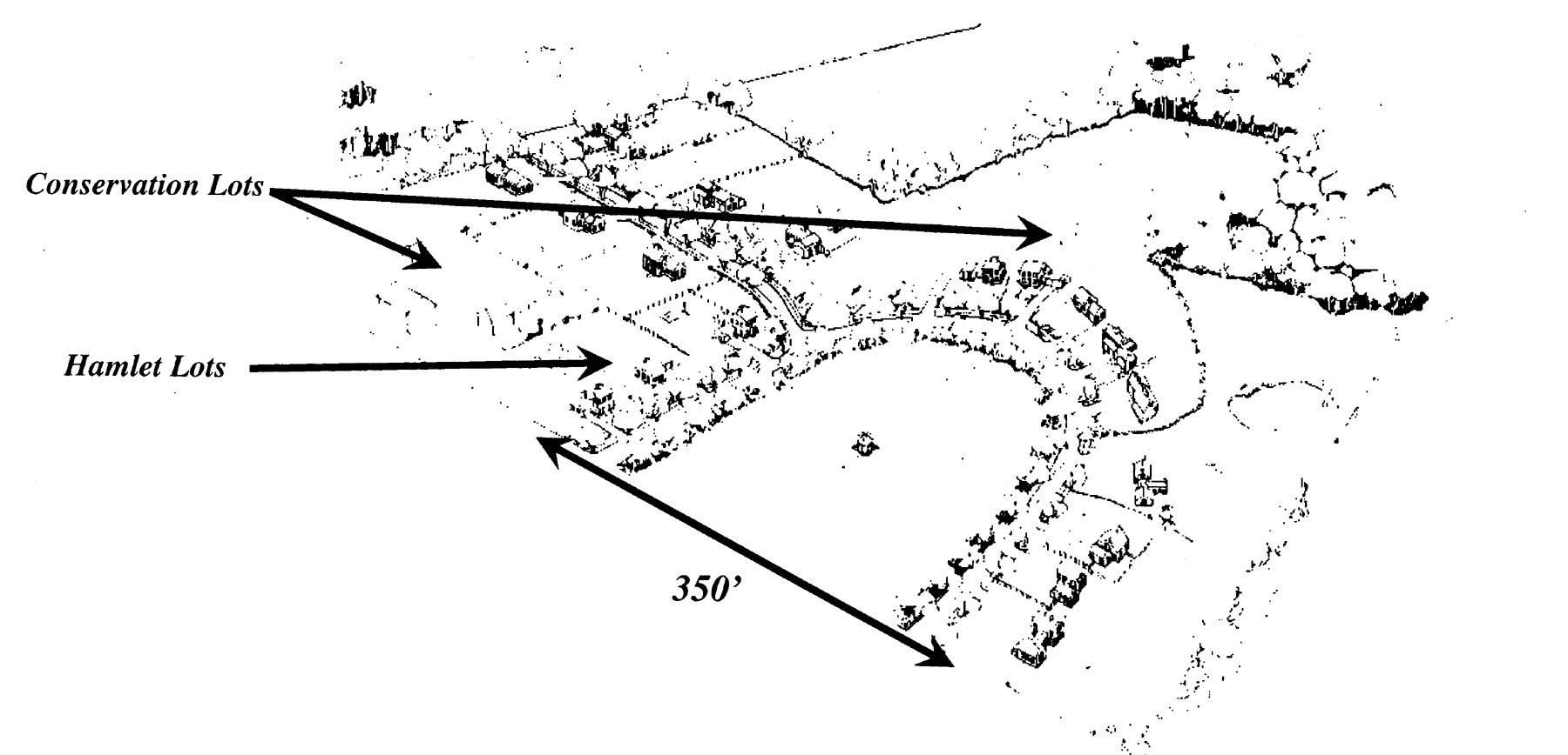
Article 4 Zoning Unified Development Ordinance Suffolk
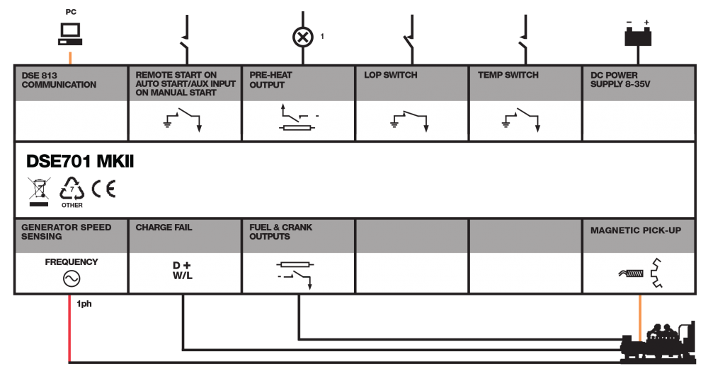
Deep sea 701 wiring diagram pdf. Deep sea electronics model 701 installation instructions the model 701 is a manual engine control module designed to control the engine via a key switch and pushbuttons on the front panel. The controller can be used in manual or auto start mode. The dse8660 is an intelligent mono display single or multi mains utility controller with automatic transfer switch capabilities. The control module synchronises single or multiple set systems in conjunction with dse synchronising load share control modules. 701 operating instructions issue issue 1 04072007 172700 jr 1 deep sea electronics plc 701 key start module operating instructions author john ruddock deep sea electronics plc highfield house hunmanby north yorkshire yo14 0ph england tel. See overleaf for overall typical wiring diagram 701 operating instructions issue issue 1 07052003 330 pm jr 9 6 dimensions 701 701hc.
The module is used to start and stop the engine and indicate fault. The module offers a range of features for single set applications including low oil pressure high engine temperature and over speed monitoring. 44 0 1723 893303 email. 44 0 1723 893303. The dse704 is an auto mains utility failure control module designed to provide a wide number of engine monitoring and protection features. The dse702 is a compact control module with an hours counter display.
The dse701 mkii is a compact control module that offers a range of features for single set applications. The module is used to start and stop the engine and indicate fault. Summary of contents for deep sea electronics plc 701 page 1 hunmanby north yorkshire yo14 0ph england tel. 44 0 1723 890099 fax. The module monitors engine temperature low oil pressure fail to start charge fail and over and under speed. 44 0 1723 890099 fax.
The typical wiring diagrams located within this document show connections for a negative earth system the battery negative connects to earth 4312 positive earth when using a dse controller with a positive earth system the battery positive connects to earth the following points must be followed.


