Table 11 software version this publication contains information proprietary to danfoss. The actual software version number can be read from par.
Vltfc 102 Hvac Drive Operating Instructions
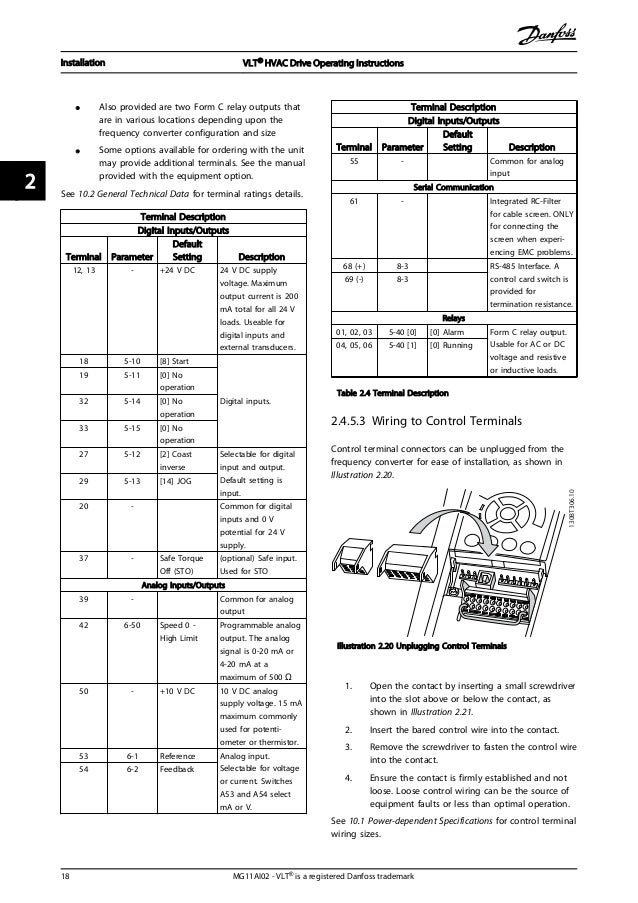
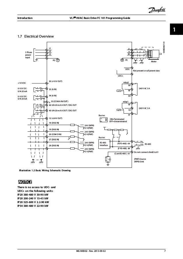
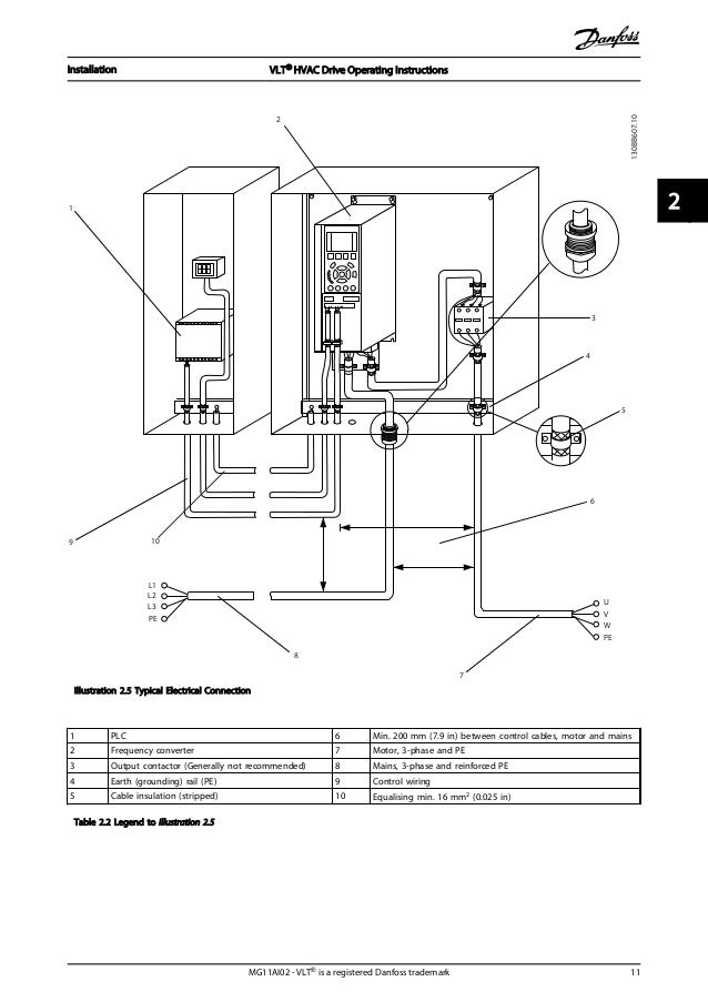
Danfoss vlt hvac drive wiring diagram. 482 wiring to control terminals 17 483 enabling motor operation terminal 27 18 484 voltagecurrent input selection switches 18 485 safe torque off sto 18 486 rs 485 serial communication 19 49 installation check list 20 5 commissioning 21 51 safety instructions 21 52 applying power 21 contents vlt hvac drive operating. 44 wiring schematic 12 45 access 14 46 motor connection 14 47 ac mains connection 17. Wait at least 4 minutes. By accepting and using this manual the user. Introduction vlt hvac drive operating instructions mg11ad02 vlt is a registered danfoss trademark 3 1 1. The vlt hvac basic drive is supplied with built in functions that reduce initial costs and increase productivity.
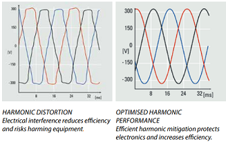
Vlt energy box software calculates as accurately as possible the cost savings and payback time of using danfoss ac drives in hvac fan and pump applications. 143 block diagram of the frequency converter illustration 13 is a block diagram of the internal. It is the most compact unit in its class. Vlt hvac drive fc 102 series this guide can be used with all vlt hvac drive frequency converters with software version 39x. Vlt hvac drive fc 102 355 1400 kw. Integrated dc coils reduce harmonics to an absolute minimum and the automatic energy optimizer saves 15 25 energy from the second you turn the it on.
175ha49011 touching the electrical parts may be fatal even after the equipment has been disconnected from mains. Design guide aj. Using vlt6002 6005 200 240 v. Vlt 6000 hvac introduction to hvac warning. 3 vlt 3500 hvac mg35b102 vlt is a registered danfoss trademark section 1 section 2 section 3 section 4 introduction to the manual for vlt 3500 hvac this manual is a tool for installation and programming the vlt 3500 hvac frequency. The actual software version number can be read from 15 43 software version.
Figure 13 adjustable frequency drive block diagram area1 line power inputtitle functions 3 phase ac line power supply to the adjustable frequency drive 2 rectifier. Vlt hvac drive fc 102 fln. 143 block diagram of the adjustable frequency drive figure 13 is a block diagram of the internal components of the adjustable frequency drive. Vlt hvac drive fc 100 series software version. See table 12 for their functions. The tool allows you to compare the energy consumption of hvac fans and pumps driven by danfoss drives with alternative methods of flow control.
Operating guide aq. Vlt hvac drive fc 102 11 90 kw. 34x this guide can be used with all vlt hvac drive frequency converters with software version 34x.
