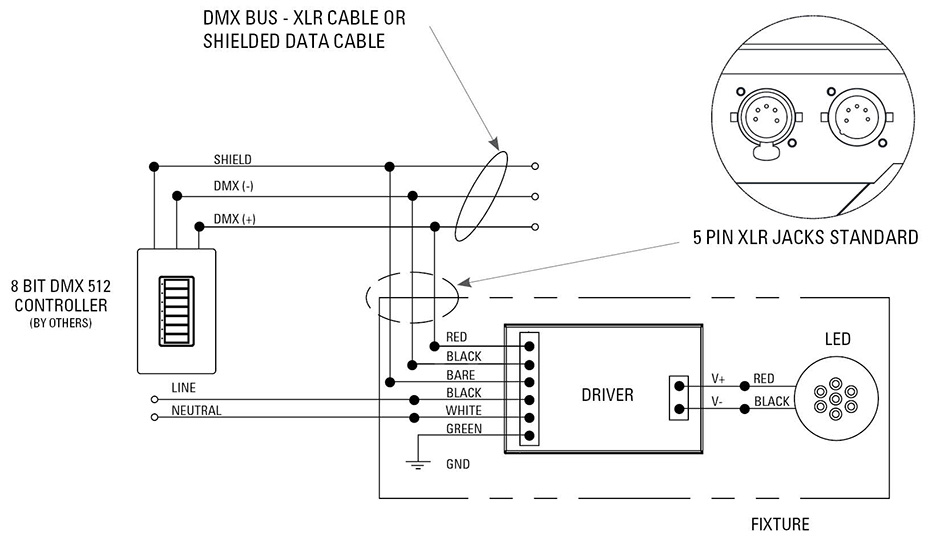
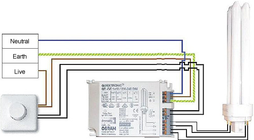
A wiring diagram is a streamlined traditional pictorial depiction of an electrical circuit. This is the system flexibility of a image i get from the dali lighting control wiring diagram collection.

Wo 9153 Building Emergency Lighting Schematic Illustrating
Dali system wiring diagram. A wiring diagram is a streamlined conventional pictorial representation of an electric circuit. Each is given an address in the dali system and the loop is connected to a dali control device. Dali wiring is the biggest advantage of the dali system. Please right click on the image and save the image. It reveals the parts of the circuit as streamlined shapes and also the power as well as signal links between the devices. Put simply the lights are wired according to the australian electrical standards with an additional twin run to accommodate full dali control.
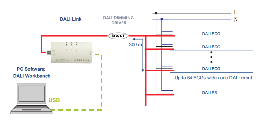
Dali control cables may be run next to the normal mains wiring to a maximum length of 300m using 15mm2 cables. Refer to our dali concepts page for more information. This is the system flexibility of a image i get from the dali lighting control wiring diagram package. You can save this photo file to your own laptop. The dali specification allows for maximum 2v drop in the communication signal. Switching off standby with dali.
The dali line is a 4 or 5 wire system requiring active neutral and two control wires. One individual network isnt enough to cover an entire building. Dali lighting wiring diagram. Preliminary schematic diagrams for the electric designerwiring basics. Collection of dali lighting control wiring diagram download variety of dali lighting control wiring diagram. Our people also have some more illustrations related to dali lighting control wiring diagram please see the photo gallery below click one of the graphics then the picture will be.
Permanent active neutral earth dali dali dali wiring consists of 2 control wires with a current limited power supply supplying a maximum current of 250ma. Wireless remote control knxenocean. It shows the components of the circuit as simplified shapes and also the power and also signal connections in between the gadgets. Collection of dali lighting control wiring diagram. Led drivers and ballasts are connected using class 1 inside the conduit or class 2 outside the conduit wiring to make up a loop of no more than 64 led drivers or ballasts. Lighting fixtures can easily be grouped.
Wiring of lighting groups with dali. Our people also have some more pictures related to dali lighting control wiring diagram please see the picture gallery below click one of the graphics then the picture will be. Knx house automation sensors measurement and. Rather several must be linked together to create a. Instead changes can be made to the system. The wiring of the ballasts regulates power to the lights does not determine the grouping of the lights and switches.
Please right click on the image and save the image. Dali topology with sensors. The dali line does not require termination of the line and supports all wiring typologies except rings and closed loops trees branches and chains are all acceptable. You can save this photographic file to your individual device. System this means that normal wiring standards are applicable.


