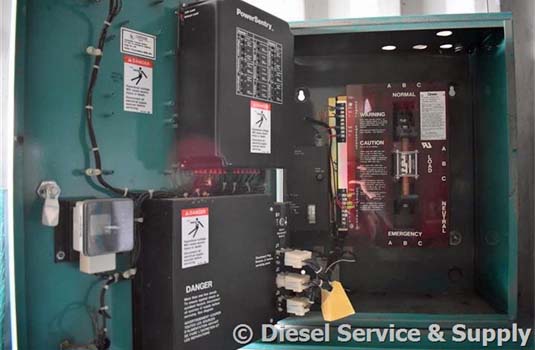
The type of entrance switch. It reveals the elements of the circuit as streamlined forms and also the power and signal links between the devices.

Cummins Onan Generator Transfer Switch Generator Transfer
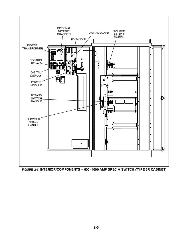
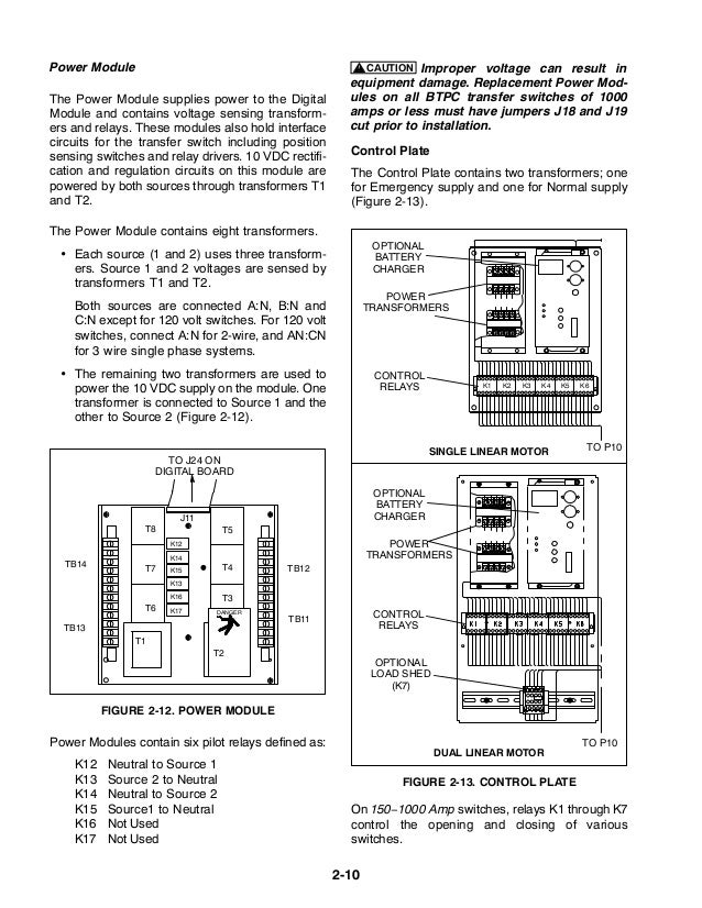
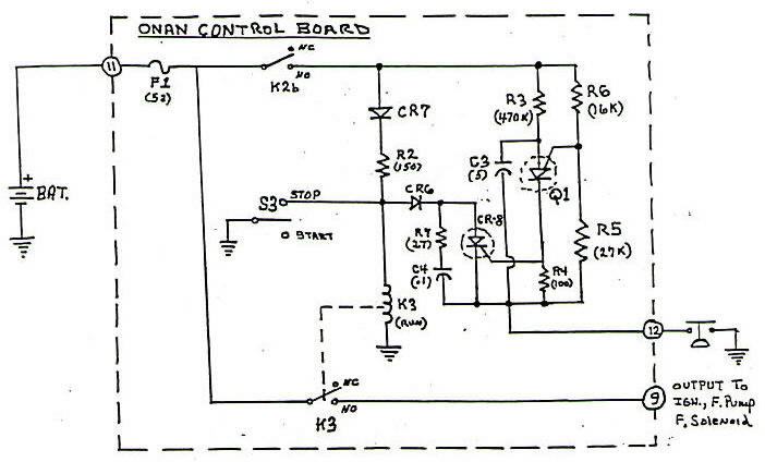
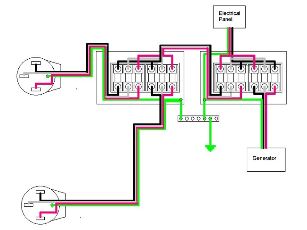
Cummins transfer switch wiring diagram. It shows how the electrical wires are interconnected and may also show where fixtures and components might be connected to the system. The location and wiring must comply with the contract drawings. Cummins transfer switch wiring diagram what is a wiring diagram. A wiring diagram is a simple visual representation in the physical connections and physical layout associated with an electrical system or circuit. Both the jumper and the diagram are supplied with the generator set. Can be used by wiring a fault indicator to the fault alarm output connector located on the front of the battery charger see figure 1.
Transfer switch must be performed only by an electrician or authorized service representative. Cummins transfer switch wiring diagram. Www page 3 of 6. Electrical wiring diagrams are made up of two points. Cummins transfer switch wiring diagram by philostrate posted on december 26 2019 october 28 2019 if you re likely to initiate a network in your home or workplace you will realize that you will need a couple of things until you are able to begin then a wiring diagram is your first and the absolute most important. A wiring diagram is a simplified conventional photographic depiction of an electric circuit.
Symbols that represent the elements in the circuit and lines that represent the links between them. A wiring diagram is a type of schematic which makes use of abstract pictorial symbols to show all the interconnections of components in a system. A 2 pin plug connec tor 323 1678 02 is shipped with the 1512 amp transfer switch battery charger. August 31 2018 by larry a. Wellborn variety of cummins transfer switch wiring diagram. This manual covers models produced under the cummins.
The transfer switch tb4 jumper must be installed in the ra series transfer switch between tb4 3 and tb4 4 according to the interconnect diagram in the ra series transfer switch owner manual.







__99834.1558655700.jpg?c=2)
