For sinking inputs connect to m shown. See appendix c spare.

Plc Siemens S7 1200 3 Phase Motor Tesla Institute
Cpu 1214c wiring diagrams. Cpu 1214c acdcrelay 6es7 214 1bg40 0xb0 24 vdc sensor power out for additional noise immunity connect m to chassis ground even if not using sensor supply. X11 connectors must be gold. ② for sinking inputs connect to m shown. 2 ai 0 10 v dc power supply. Cpu 1214c wiring diagrams table 1. 14 di 24 v dc.
② for sinking inputs connect to m shown. Hi i am using the internal 24vdc to supply all of my inputs and outputs. For sourcing inputs connect to m. X11 connectors must be gold. Ac 85 264 v ac at 47 63 hz programdata memory 100 kb. 14 di 24 v dc.
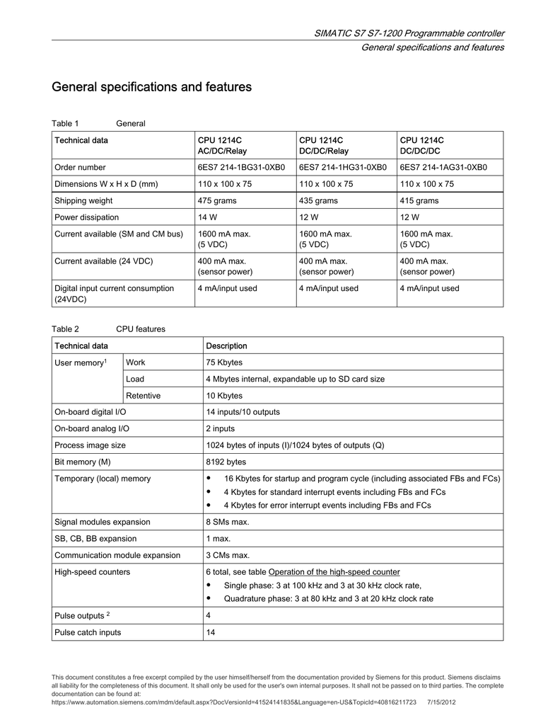
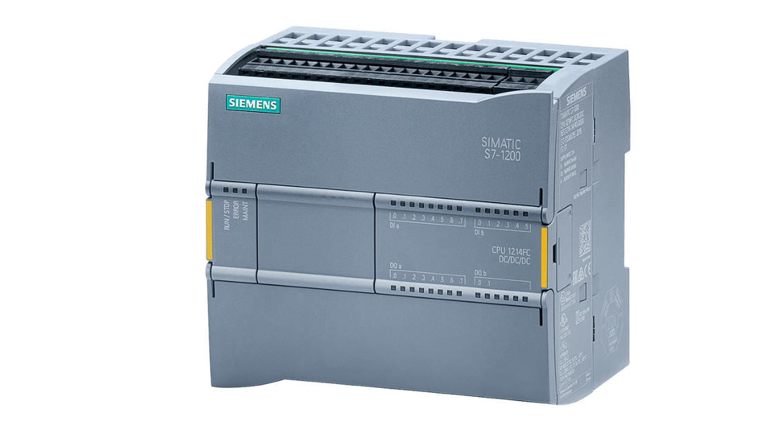
Simatic s7 1200 cpu 1214c compact cpu acdcrelay onboard io. Dc 204 288v dc programdata memory 100 kb. 10 do relay 2 a. X11 connectors must be gold. Simatic s7 s programmable controller. Step 7 v13 basic and professional page 35 s7 1200 cpu firmware release v40 for a complete list of the s7 1200 products described in this manual refer to the technical specifications page 829.
For sourcing inputs connect to m. ② for sinking inputs connect to m shown. Siemens industry catalog automation technology automation systems simatic industrial automation systems controllers basic controllers s7 1200 central processing units standard cpus cpu 1214c. 1 ma input delay for rated value of input voltage. Wiring diagrams for siemens nema contactors and starters. 10 do relay 2 a.
Simatic s7 s7 1200 programmable controller cpu 1214c wiring diagrams cpu 1214c wiring diagrams table 1 cpu 1214c acdcrelay 6es7 214 1bg40 0xb0 ① 24 vdc sensor power out for additional noise immunity connect m to chassis ground even if not using sensor supply. Cpu 1212c wiring diagrams table 1 cpu 1212c acdcrelay 6es7 212 1be31 0xb0 ① 24 vdc sensor power out for additional noise immunity connect m to chassis ground even if not using sensor supply. 2 ai 0 10 v dc power supply. Cpu 1214c wiring diagrams. 6es7214 1hg40 0xb0 cpu 1214c dcdcrelay 14di10do2ai simatic s7 1200 cpu 1214c compact cpu dcdcrelay onboard io. For sourcing inputs connect to m.
See appendix c spare. Dear membersmay be i am asking a stupid question but i am new in this field so a lil bit shyactually i am working on positioning of a servo drive estun edb 15ama with 1214c cpui want to know about the inner diagram of of digital outputs of cpu 1214c. Certification ce label c tick and other standards refer to the technical specifications page 829 for more information. Cpu 1214c wiring diagrams table 1 cpu 1214c acdcrelay 6es7 214 1bg31 0xb0 ① 24 vdc sensor power out for additional noise immunity connect m to chassis ground even if not using sensor supply. Cpu c wiring diagrams cpu c wiring diagrams table 1 cpu c acdcrelay 6es7 bgxb0151.


