After initial wiring is complete check wiring diagram to verify power pack is wired correctly. 52013 ordering information installation notes specifications 120277vac 5060hz voltage input secondary voltage of 24 vdc secondary output of 225 ma.

Asickle 7 Holm
Bz 50 wiring diagram. Plenum rated the bz 50 power pack is comprised of teflon coated low. Bz 50 12 24vdc at 36ma s 120 12 24vdc at 36ma. The rc version includes an integrated rj45 jack. For the bz 50 low voltage wiring should use at least 22 gauge wire. Wiring terminations7 color coded 14 awg pigtails rated at 300vac. Installation diagram bz 50 bz 50 u bz 50 fta 120230277vac.
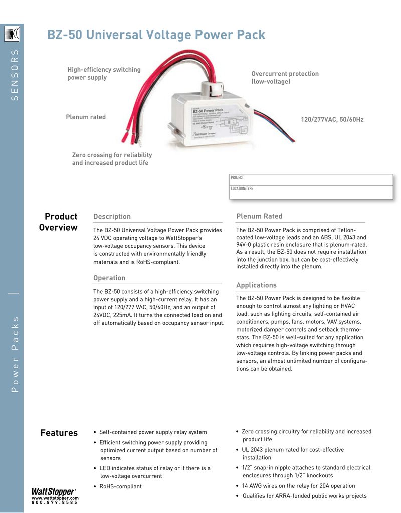
It has an input of 120277 vac 5060hz and an output of 24vdc 225ma. Short circuit current sccrnot specified. The bz 50 is comprised of a relay with line voltage contacts and a 24 vdc power supply enclosed in a simple unit. 2 wire push button red 24vdc grey manual on 3 wire momentary dcc2 red 24vdc grey manual on install jumper wire. Input voltage ballasta incana motorhp output 1 all wattstopper power packs should be installed in accordance with state. The direct current 24 volt supply features short circuit and overcurrent.
This device is rohs conforming. Low voltage wiring should use at least 22 gauge wire high voltage connections should use at least 14 gauge. Improper wiring can cause damage to power pack lighting system and. The bz 50 consists of a high efficiency switching power supply and a high current relay. Bz 50 blue black red switch optional lighting load black any 3 wire 24vdc sensor line red high voltage connection made inside j box power pack system layout wiring pub. Installation diagram low voltage momentary switch options by using two low voltage switches a ceiling sensor and two bz 150s one set to auto on and one set to manual on bi level switching with manual on operation can be achieved.
Make sure power has been turned off at the circuit breaker. Always check local building codes. Operating temperature32 to 104 0 to 40 operating humidity10 to 95 rh non condensing. After initial wiring is complete check wiring diagram to verify power pack is wired correctly. Local and national electrical codes and requirements. The bz 50 power pack is attached to existing junction boxes or mounted into fixture wiring trays.
It turns the connected load on and off automatically based on occupancy sensor input. Visual indicationbz 50 red led shows relay status. The bz 50 universal voltage power pack provides 24 vdc operating voltage to wattstoppers low voltage occupancy sensors.
