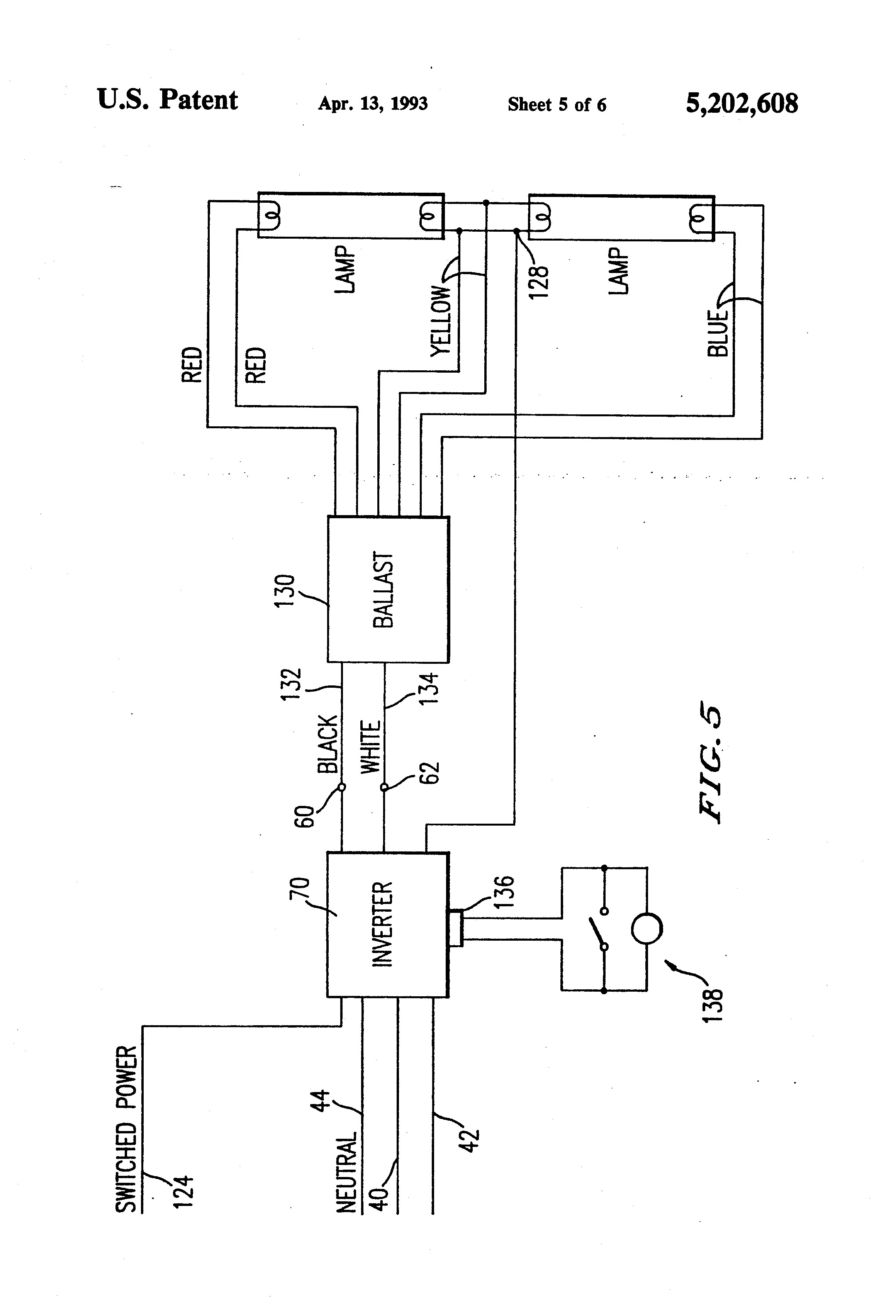
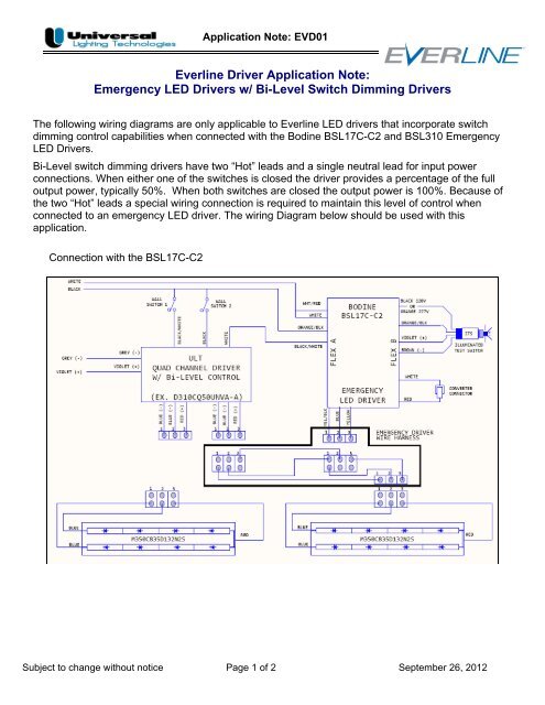
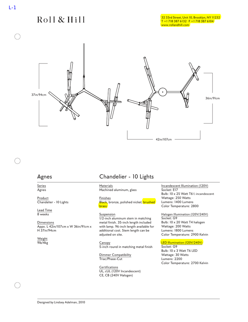
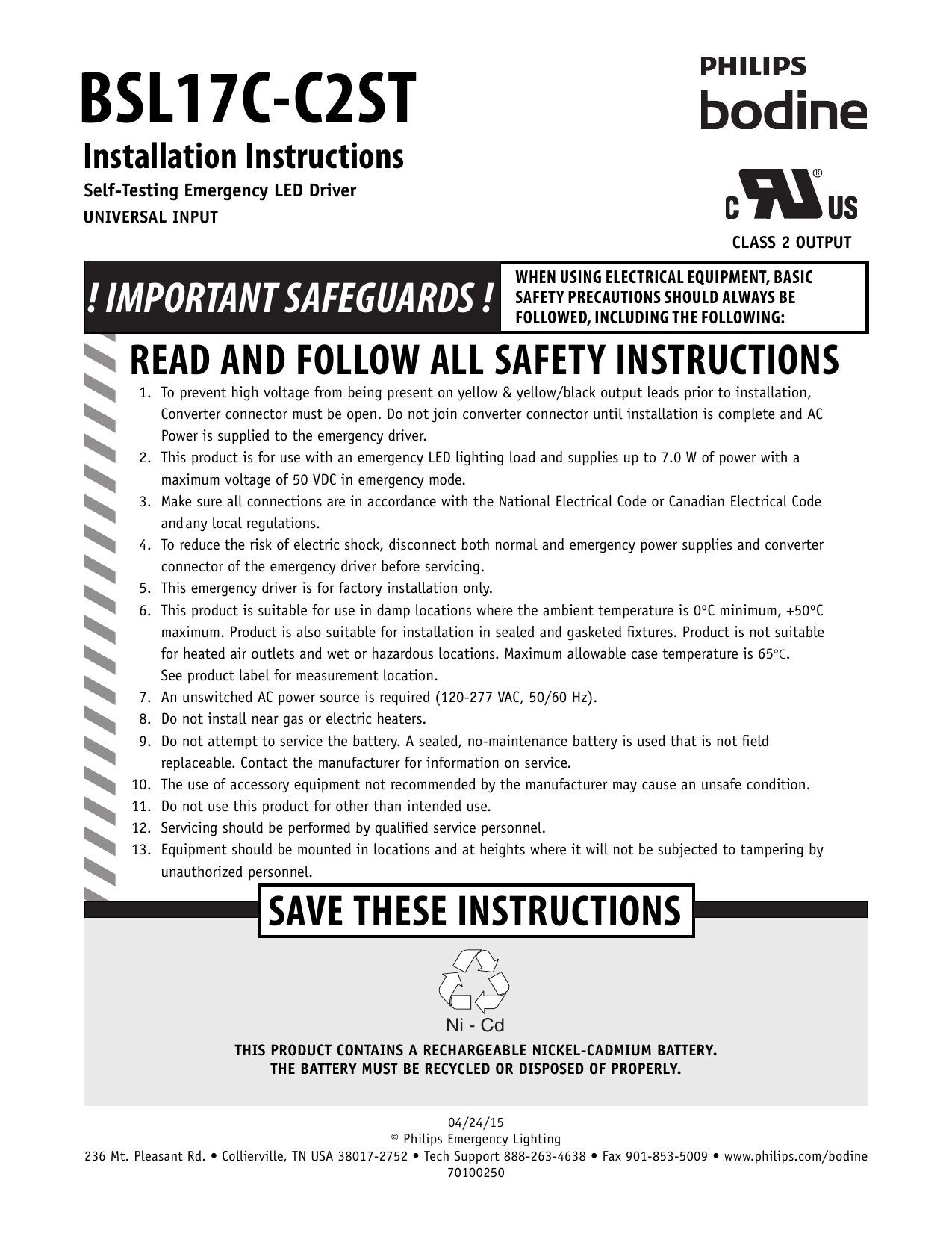
Select the appropriate wiring diagram to connect the emergency driver to the ac driver and led load. May be used with other drivers.

Ow 4941 Bodine B90 Emergency Ballasts For Sale
Bsl310c wiring diagram. Ul and code compliance the bsl310 has been tested by underwriters laboratories in accordance with the standards set. 2 wire input reduces wiring errors compatible with a variety of led strip manufacturers compatible with ac drivers and led loads rated for class 2 selectable output rohs compliant 140 225 118 145 dimensions 145 x 225 x 118 mounting center 140 led bsl310. Do not join converter connector until installation is complete and ac power is supplied to the emergency driver. Dimensions bsl310cm 1534 x 225 x 116. Consult the factory for other wiring diagrams. Make sure all connections are in accordance with the national electrical code and any local regulations.
Make sure the necessary branch circuit wiring is available. Contains the illuminated test switch wiring in its own conduit with the test switch and a wall plate included in a separate parts kit. Wiring diagram 4 maximum load voltage load select 10v 29v connected 30v 50v not connected fig a two 2 wire integrated test switch wall switch hot whtred. Wiring diagram electrical wires cable schematic philips bsl310 emergency ballast by philips bodine 13522d6 bodine b50st emergency ballast wiring diagram library emergency led drivers w universal lighting technologies wiring diagram electrical wires cable schematic philips bsl310 emergency ballast by philips bodine 13522d6 bodine b50st emergency ballast wiring diagram library emergency led. Wiring diagrams options 4 fig b bsl310c df b illuminated test switch on wall plate ac driver white whtblk common yellow yelblk blue led led ac driver ac driver led load white black wall switch hot whtred red converter red. Bsl310cbsl310m 010516 ni cd universal input class 2 output 1.
An unswitched source of power is.


