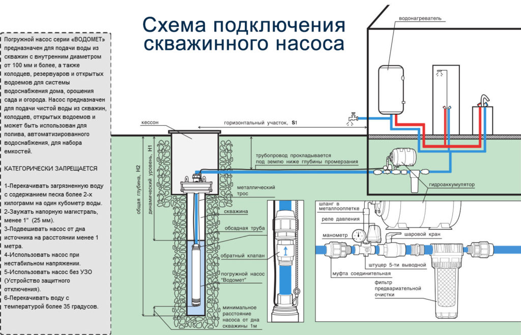
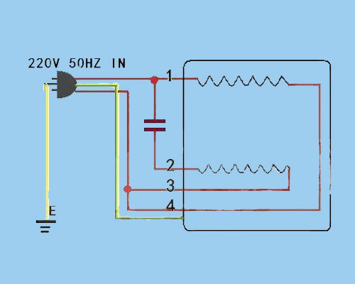
Why we called a single phase submersible motor a 3 wire submersible that we also know that we have two wire in single phase power supply. 3 wire submersible pump wiring diagram wellread.
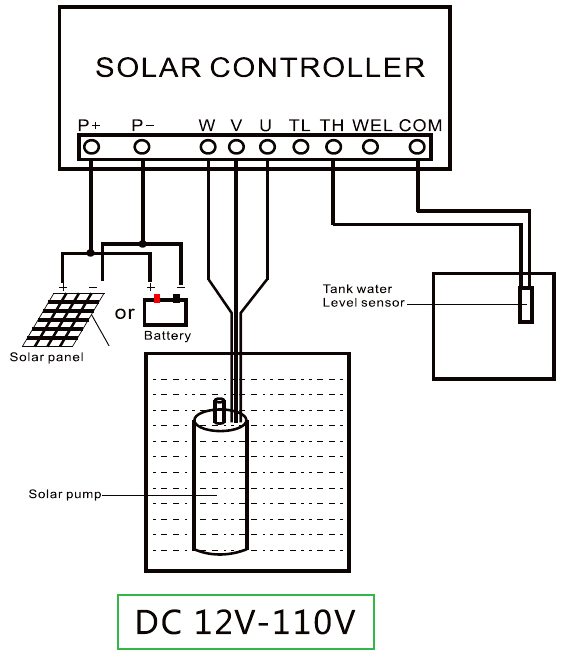
750w 72v Dc Solar Water Pump
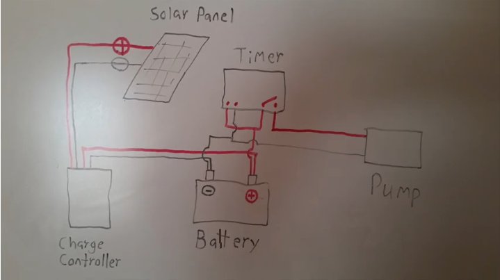
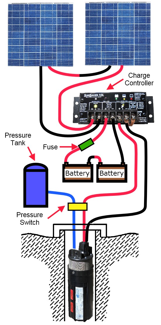
Borehole pump wiring diagram. Submersible well pump accessories installation diagram. 14 gauge wire is fine for providing power from your house to a standard household pump circuit. The green ground wire should also be terminated to the box and a ground coming from the panel. 3 phase submersible pump wiring diagram. All well pumps come with a wiring diagram which provide specific instructions for your specific pump. If your pump is submersible special wire is sold to go from outside your home down into the well and to your pump.
Assortment of submersible pump control box wiring diagram. 3 wire submersible pump wiring diagram collections of submersible well pump wiring diagram wiring diagram collection. The gauge of this wire is at least 14. Today i am hear to write about submersible pump control box wiring diagram in this post you will complete understood about 3 wire submersible pump wiring diagram which is an single phase submersible pump motor. After determining the voltage is zero disconnect the motor wires directly from the pressure switch box m1 and m2. Three wire submersible well pump typical installation.
Wiring a pressure switch is simply breaking the circuit power through the pressure switch contacts. The diagrams for both the two and three wire pumps can be downloaded using adobe. In most cases if the leads are the same color then the polarity does not matter but check this with the installation sheet and wiring diagram. To replace the two wire pump. Ultimately using some simple electrical tests the homeowner traced the water pump problems to a nicked well pump wiring circuit wire. Well pump wiring diagnosis repair.
Ask a question about diagrams typical pump installations. Single phase wiring diagrams single phase wiring diagram for 05hp pumps with governor switch single phase wiring diagram with governor switch single phase wiring diagram without governor switch three phase wiring diagrams three phase 208v wiring diagram three phase 230v wiring diagram three phase 460v wiring diagram three phase 575v wiring diagram kb pump wiring diagrams kb pump 230v wiring. Not only a contactor but also i install the thermal overload relay which will protect the motor form burning in case of over current flow to the circuit. Im not sure of the size exactly but theres only one kind of wire sold for going. This article describes troubleshooting a submersible well pump that was causing tripped circuit breakers and that pumped water only at a slow reduced rate and pressure. Well pump control box wiring diagram awesome wonderful franklin.
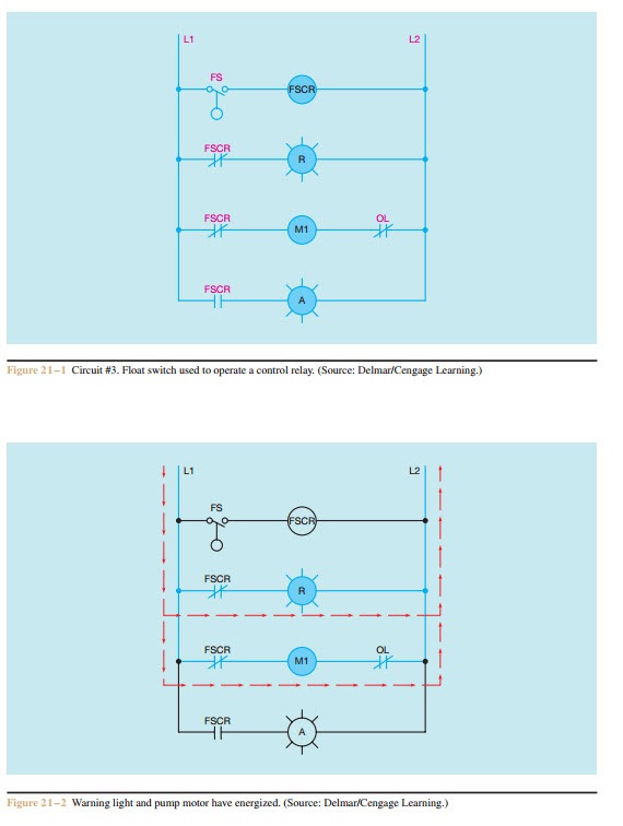
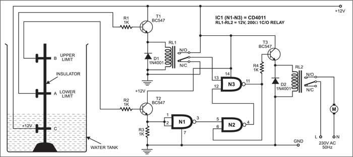
In which i control a three phase submersible pump motor using magnetic contactor. Click on the image to enlarge and then save it to your computer by right clicking on the image. Shallow well jet pump system booster installation diagram. Submersible pump control box wiring diagram submersible well pump wiring diagram. Submersible motor starter wiring diagram inspirationa 3 wire.
