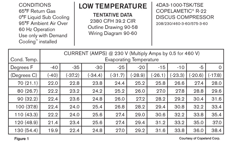
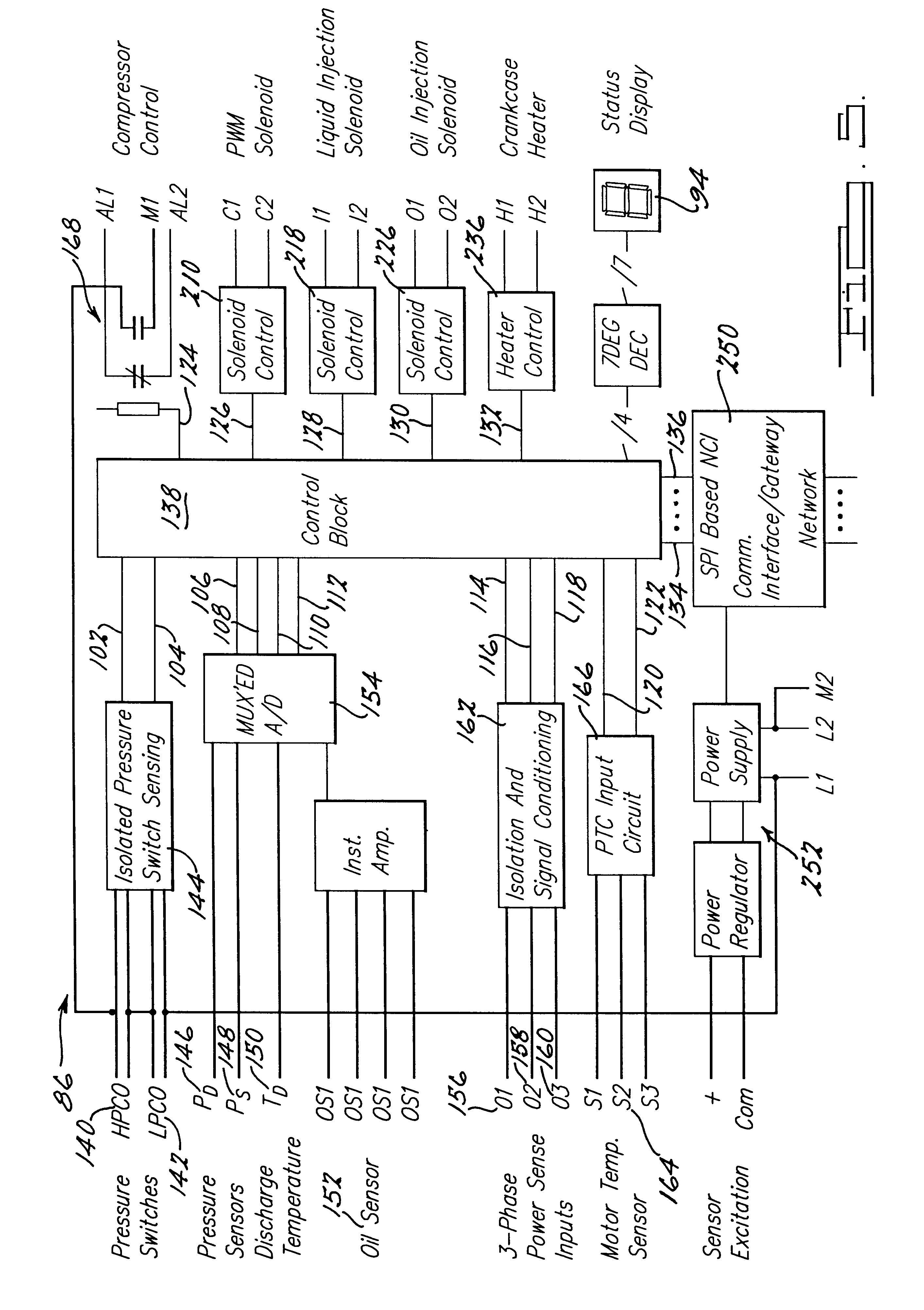
Figures 1 through 4 for wiring diagrams. Do not operate compressors unless compressors are correctly charged with bitzer bse60k oil.

Wiring Diagram For Freezer Room Diagram Base Website Freezer
Bitzer compressor wiring diagram. It protects the compressor from operating under critical conditions. 1 or 2 4 cylinder compressors for each compressor the plc module requires a separate analog 0 10v signal from the rack controller to terminals i7 andor i8. Wiring diagrams and check the connections for tight seat. Refer to the extensive bitzer reciprocating compressor range using bitzer selection software to provide the correct selection for you specific application. Further compressor detail is available from the bitzer selection softwarejun 24 an a 1 compressor technical video for service technicians on how to wire a 9 lead v copeland compressor for part wind start in the field. The engine and discharge gas temperature oil supply and application limits.
Compressor configuration this bitzer maxi rack employs bitzer ecoline compressors and or bitzer varispeed compressors providing outstanding performance reliability and efficiency. The module switches the oil heating on and off and depending on the equipment of the compressor the start unloading the compressor cool. Do not operate compressors system until in line valves controls are set for operation. Do not operate compressors unless the crankcase heaters are installed. Risk of burns or frostbite. 34 wiring diagramspower connection 55 4 accessories options 41 protection devices se b3 delta pii olck1 59 42 other oil monitoring devices 65 43 refrigeration oils 66.
Electrical connection wiring diagrams. For work on the compressor once it has been put into operation caution surface temperatures of more than 60c or be low 0c. A 24v jumper from the power supply to terminal i1 i2 or i3 is required to select the minimum allowable capacity. Bitzers intention is that all electric work is performed by qualified and. Authorized staff all work on compressors and refrigeration systems should only be. The cables and terminals of the ptc control cir cuit must not come into contact with the control voltage or operating voltage.
Ers of the reciprocating compressor.


