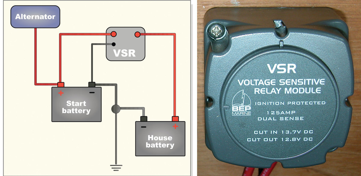
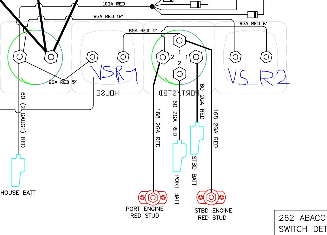
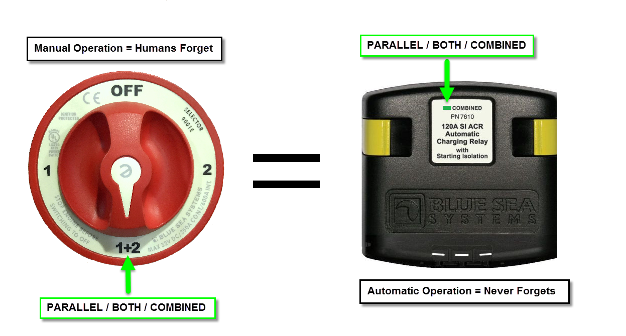
A bep marine vsr wiring diagram can be a compacted main stream picture representation of an electrical circuit. 7 0 25a single sense vsr operation the voltage sensitive relay vsr allows two batteries to be charged at the same time.

Mo 6600 Wiring Diagram For Bep Marine Battery Switch
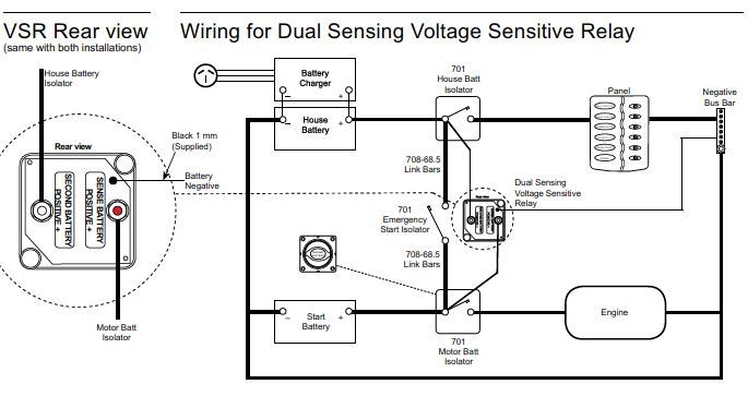
Bep marine vsr wiring diagram. It had somewhere around 12000 hours of parallel combined use on a world cruising boat with solar wind alternator and genset charging. Simple to install 3 wire connection leaves alternator wiring intact no volt drop vs diode isolators ignition protected surface or panel mountable replaces previous models 710 125a and 710 125a ds multi voltage auto selects between 12 and 24v dc operation digital circuits provide very low power consumption and enhanced performance. It shows the components of the circuit because simplified contours and also the signal and power connections between those apparatus. It reveals the parts of the circuit as simplified forms as well as the power and also signal connections in between the tools. This system is designed for triple outboard installations. Hi i would definitely use a voltage sensitive relay system over an isolator in your application.
A wiring diagram is a simplified standard pictorial depiction of an electrical circuit. In this image we are looking at the guts of a combinervsr that was 7 years old. Have i oversimplified the issuedecision or perhaps ive missed something and its more complicated. The 719 140a dvsr was designed through popular demand for our 717 140a dvsr cluster. Every product it makes meets exacting performance specifications and is designed to withstand extreme conditions both at sea and on land. Now thanks to beps unique vsr voltage sensitive relay boat owners can enjoy the benefits of fully charged engine starting batteries and deep cycle house batteries with one easy to install charging system.
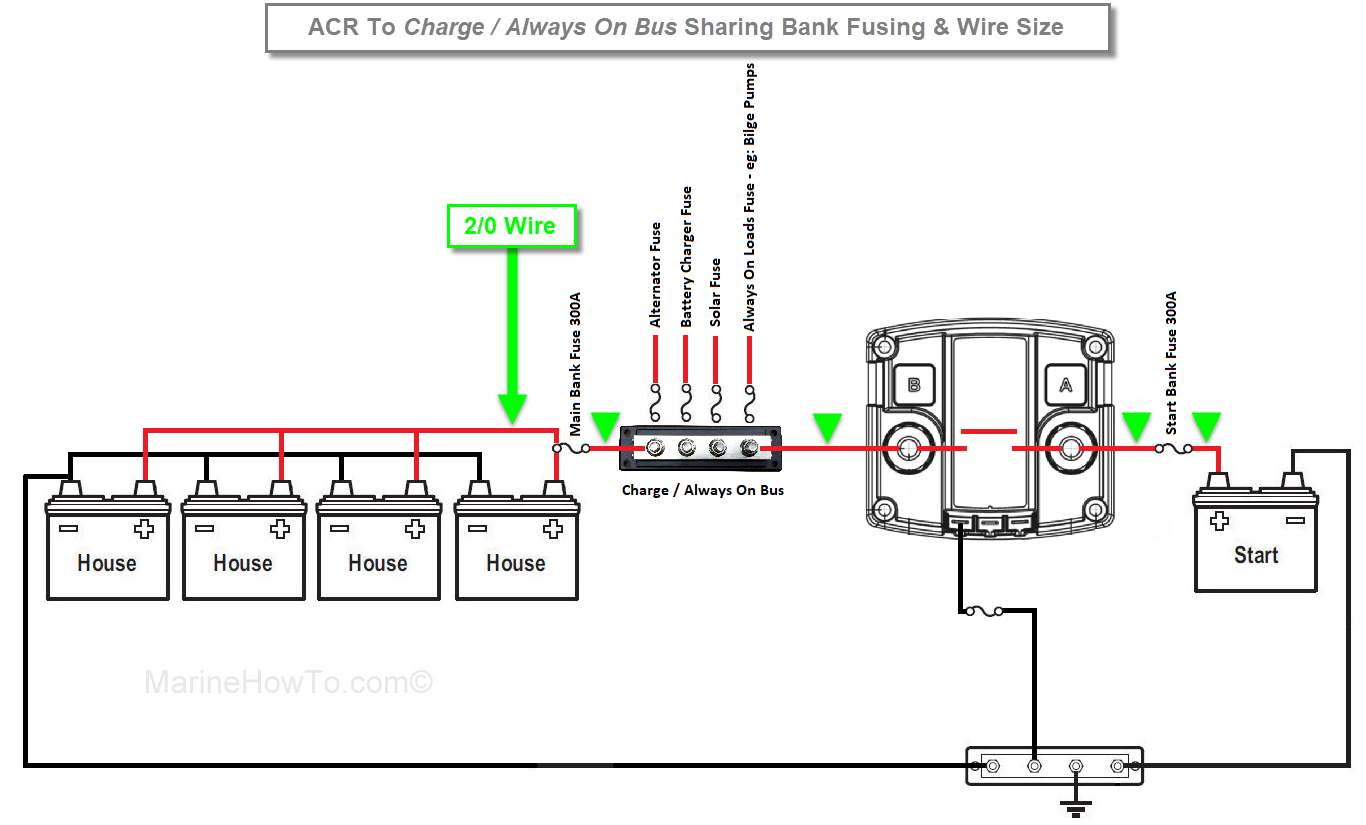
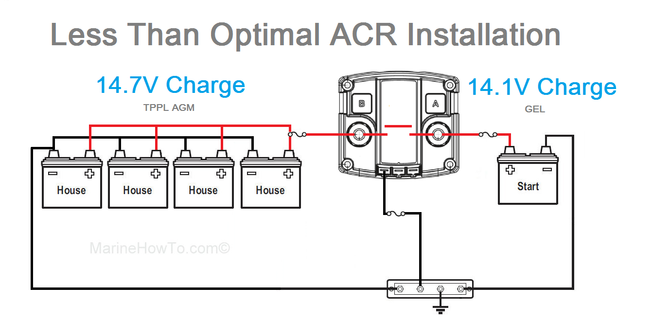
As can be seen the contacts are still in perfect condition even after 7 straight years of 247365 world cruiser live aboard life. 125 amps continuous 140 amps intermittent ignition protected ul 1107 auto voltage sensing 12vdc or 24vdc max 32vdc power consumption standby 18ma 16ma at 24 vdc power consumption storage mode 0ma cut incut out voltages 134v 268v 128v 256v. Also saw a nice diagram of the wiring but you used both a vsr and an isolator. Once again using multiple vsrs off each start battery giving combined charge from all 3 outboards into the house battery via vsrs. Collection of bep marine battery switch wiring diagram. Cc twin eng bat sw dvsr combo 2x3 mod compare prev 1 next.
Bep engineers and manufactures a range of high quality electrical solutions designed for the harsh marine and rv environments.
