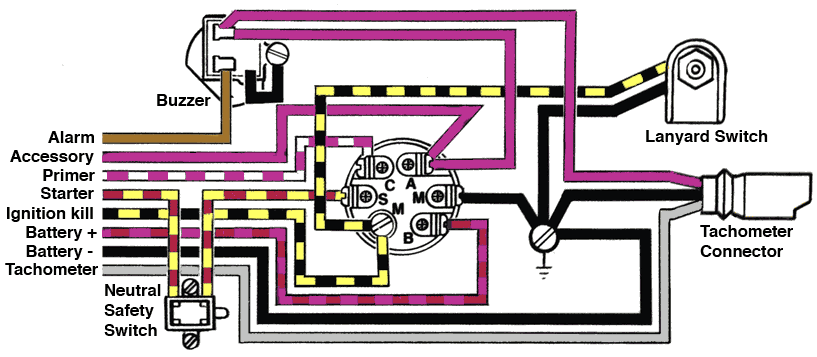
The main purpose of the switch is to allow the operator to safely engage the ignition system and activate the electric starter. See how the anti.
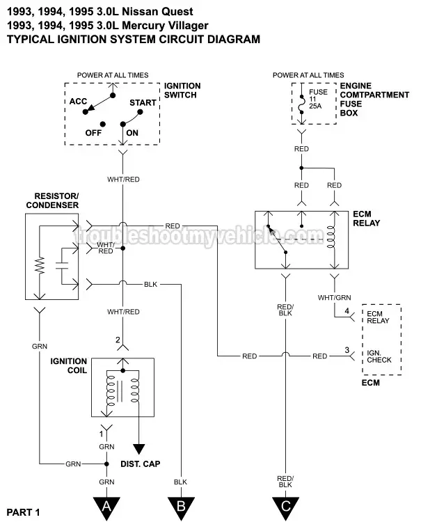
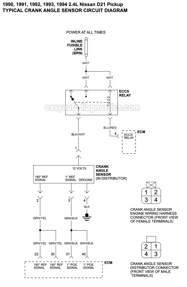
Part 1 Ignition System Wiring Diagram 1993 1998 3 0l Nissan
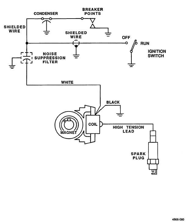
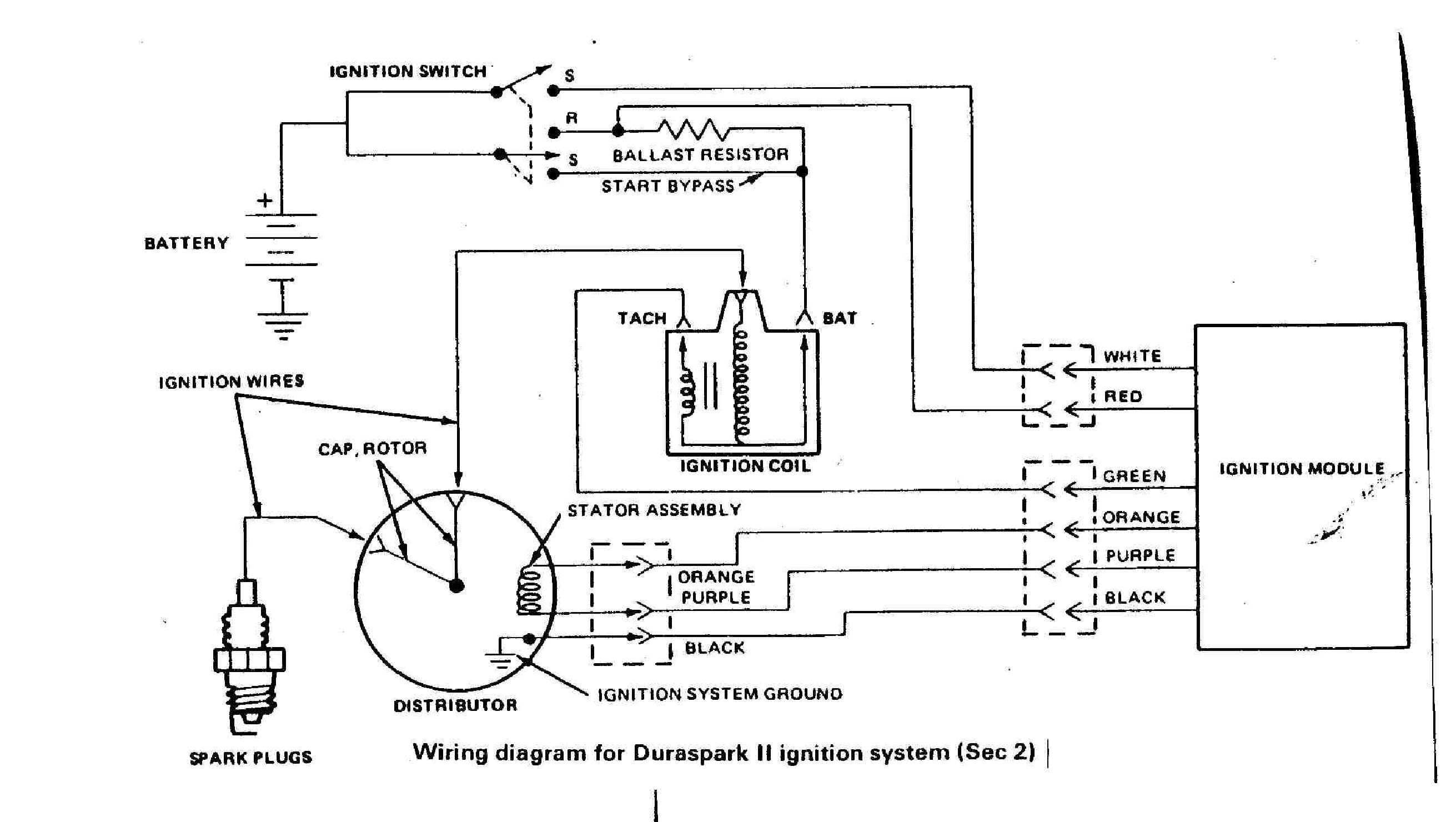
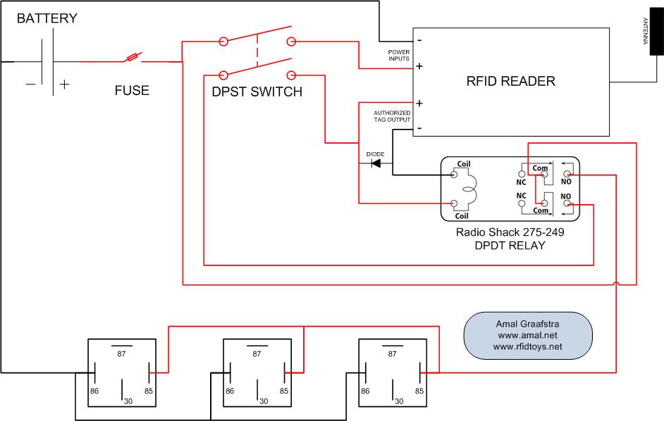
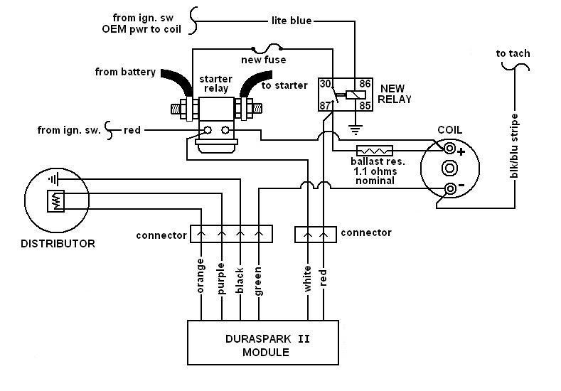
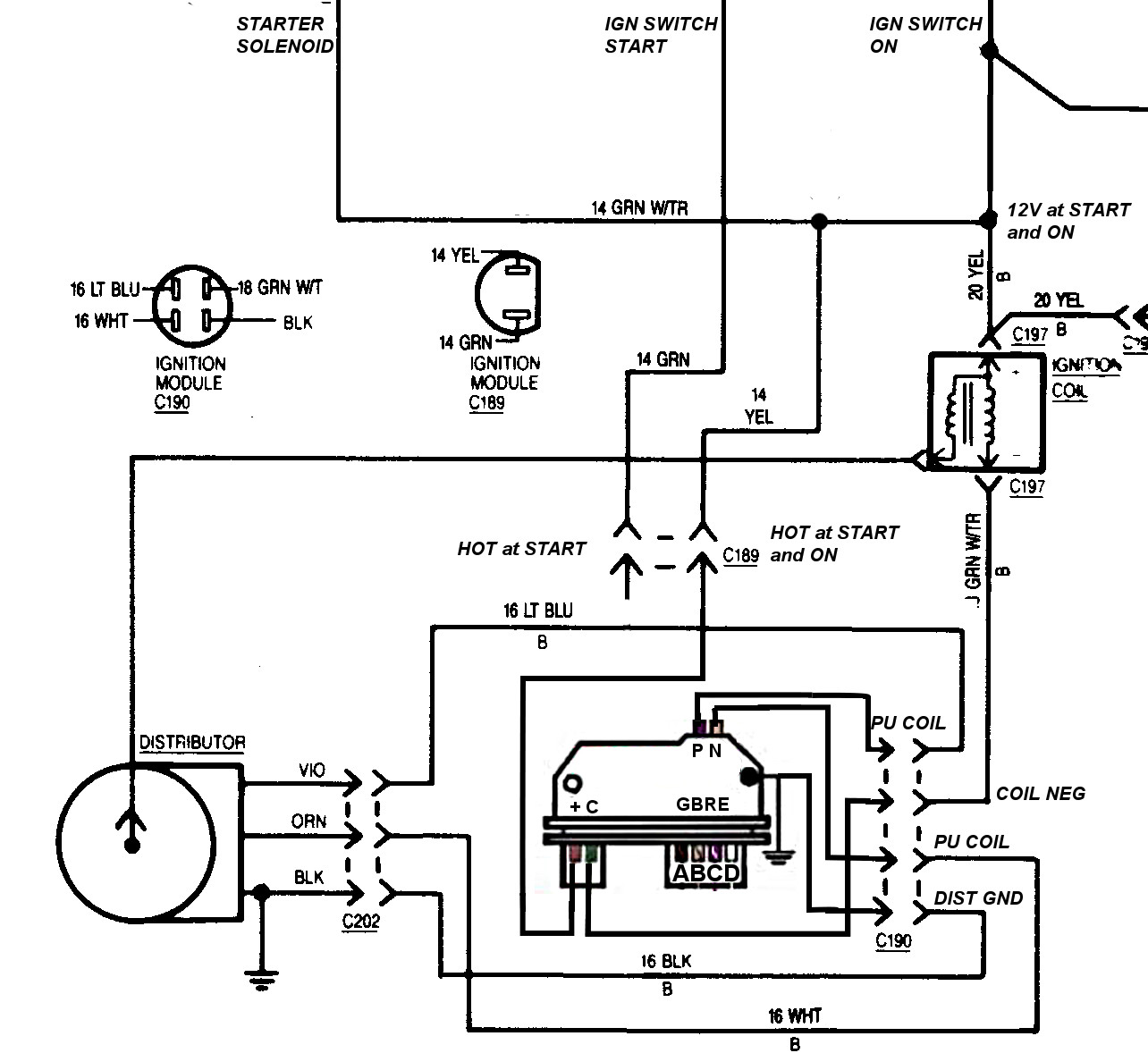
Basic ignition wiring diagram. Briggs stratton sells electrical components only for engines. Once the voltage is stepped up it goes to the secondary circuit which then directs the charge to the correct spark plug at the right time. Motorcycle wiring boat wiring electrical circuit diagram automobile volkswagen electrical engineering electric cars. The ignition coil is the component that converts the 12 volt signal into the high 20000 volt charge. This diagram was designed for 12 volt systems but can also be used for 6 volt systems. The ignition switch in a motor vehicle is the main electrical component used by the operator to start run and turn off the vehicle.
Basic ignition switch wiring diagram thanks for visiting our site this is images about basic ignition switch wiring diagram posted by maria rodriquez in basic category on may 06 2019. This applies to all old cub cadet ford jacobsen john deere wheel horse case and simplicity garden tractorsnbsp. Hot rod wiring diagram please note. The color will be noted using abbreviation beside each wire following the exact same pattern. For example a white wire with a black stripe on the side would be identified as whtblk. If you have experience with basic repair brake pad replacement can be done in 4 hours.
We did our best to keep this as simple and as easy to understand as possible. Replacement of the ignition switch becomes necessary when. If used for 6 volt make all the wires heavier by 2 gauges. Here is a basic wiring diagram that applies to all vintage and antique lawn and garden tractors using a stator charging system and a battery ignition system. Family handyman car truck. Before we begin this discussion lets talk a bit about electricity in general.
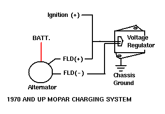
For example 14 gauge wire will become 12 gauge 10 gauge will be 8 gauge etc. Tractor ignition switch wiring diagram see how simple it lookswhen you strip all the other stuff away. Learn to navigate this systems wiring circuitry and diagram using current flow analysis relay and module operation and neutral switch actuation such as circuit completion. If you are replacing or rebuilding parts of the small engine on your lawn mower snow blower or other outdoor power equipment the basic schematics or wiring diagrams of our alternator systems are available in our guides below. An ignition switch wiring diagram provides the schematics that are needed to enable auto owners to fix any wiring repairs related to their ignition system. Colors often differ from one car manufacturer to another but the code used to identify them in car wiring diagrams is always the same.
