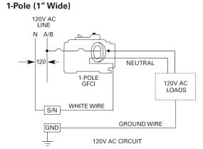
With a standard circuit breaker there is only one wire connected to the breakerthe circuits hot wire. This circuit breaker wiring diagram illustrates installing a 20 amp circuit breaker for a volt circuit.
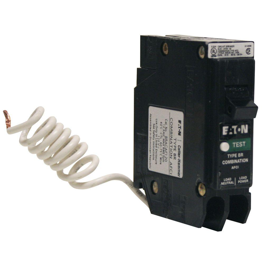
Eaton Br 15 Amp Single Pole Combination Arc Fault Circuit Breaker
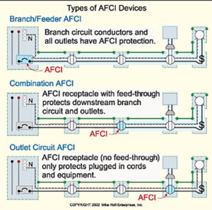
Afci breaker wiring diagram. In today post we will show the different wiring diagrams for afci combination switch with outlets light switches and other components and devices to protect the residential areas from unintentional arc fires. Electric circuit protection with afci provide the extra measure of safety for your familyafcis are installed serving required house wiring circuits protecting areas such as the bedrooms. In our previous posts we have learned different types of afci wiring diagrams such as afci circuit breaker afci outlet. Here in edmonton alberta i believe that for every line coming from the circuit breaker box it allows a maximum of 12 outletslights combined. This circuit breaker wiring diagram illustrates installing a 20 amp circuit breaker for a 240 volt circuit. The conventional circuit breaker has thermal and instantaneous sensing functionality.
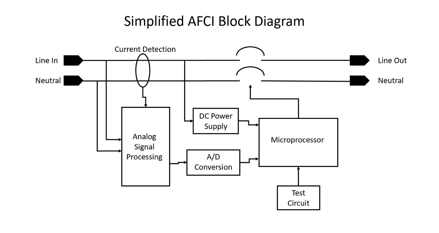
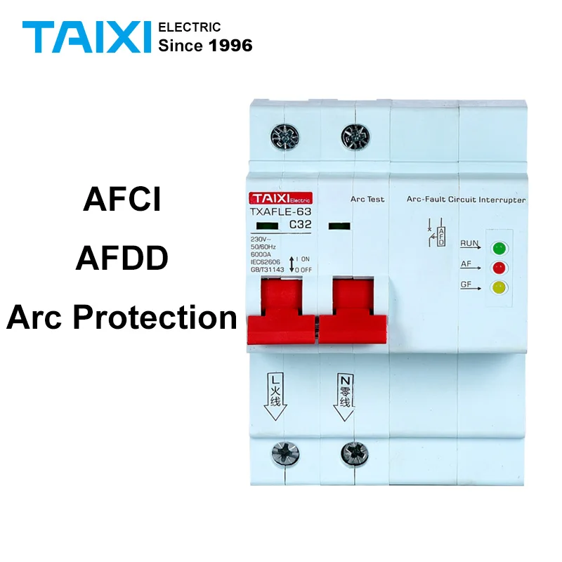
Each afci breaker involves three electrical connections. Single pole afci circuit breaker the afci electronics can function independently from the conventional circuit breaker. Arc fault circuit interrupter breakers prevent fires by sensing when an electrical arc is about to occur and instantly disconnecting the damaged circuit before the arc builds enough heat to catch firestandard circuit breakers dont always trip in these instances because standard breakers are designed to respond to a sustained amount of heat not a quick surge. I understand that bedroom power outletsplugs are now being required to have an afci. The below illustration is a block diagram of a single pole afci circuit breaker. Arc fault circuit interrupter afci breakers prevent fires by sensing when an electrical arc is about to occur and instantly disconnecting the damaged circuitwiring for a 20 amp volt appliance circuit breaker.
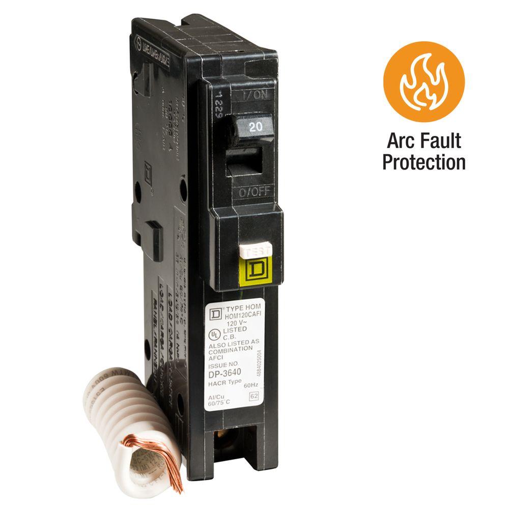
Our afci photo at left illustrates a square d 20a afci breaker during installation in the electrical panel. Fault circuit breaker to. A neutral wire is not used in this circuit. Keep in mind that according to nec 2014 afci is must to. In this four wire afci wiring diagram two lines as l1 and l2 has been connected to the input terminals of afci breaker and the builtin white is connected to the neutral busbar in the mains supply. Typical wiring details for afci circuit breakers.
Afci protects the bedroom circuit devices against the danger of arcing which can lead to fire. The 122 gauge cable for this circuit includes 2 conductors and 1 ground. How afci arc fault circuit interrupters and outlets are wired electrical question. But with both afci and gfci circuit breakers both the hot and neutral circuit wires are attached directly to the breaker while a separate coiled pigtail wire from the breaker is connected to the neutral bus bar in the panel. The white wire is used for hot in this circuit and it is marked with black tape on both ends to identify it as such. The light green arrow points to the afci device youll notice that it is much longer than conventional circuit breakers in the panel.




/Combo-AFCI-GFCI-567c60cf5f9b586a9e9cde5c.jpg)


