Acs800 01u1 acs800 04u4 acs800 11u11 acs800 31u31. Actual value selection for fieldbus when a type rxxx fieldbus adapter is used 207 block diagram.

En Acs800 104 Hw Man F
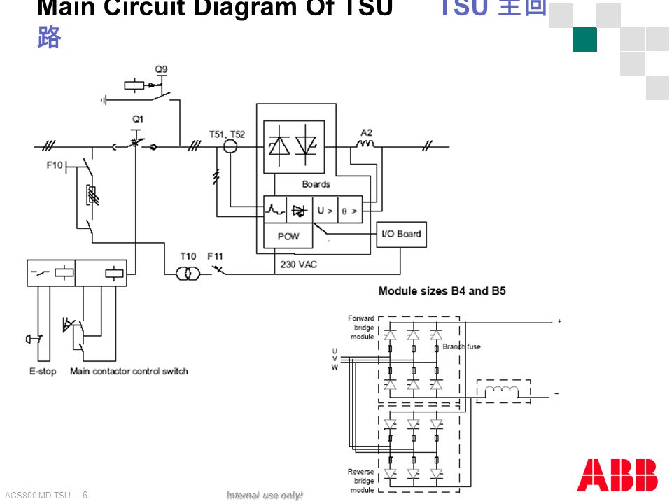
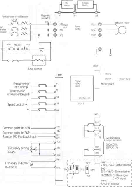
Acs800 wiring diagram. Brake chopper and resistor installation below is a simple example wiring diagram. Safety relay type bd5935 has been approved by abb for connections to the drive see chapter installation of agps board prevention of unexpedted start q950 or the circuit diagram delivered with the drive acs800 07u7. Connection example 24 vdc 4 20 ma two wire sensor. For manuals not available in the document library. Abb acs800 drive wiring diagram. Depending on the external wiring dangerous voltages 115 v 220 v or 230 v may be present on the terminals of relay outputs ro1 to ro3.
Selecting the power cables. Abb acs800 drive wiring diagram. L1 l2 fuses acs800 u1 v1 w1 thermal switch standard θ in abb resistors resistor braking phone. How to control the drive through the io interface. Acsu104 c drives to kw to depending on the external wiring dangerous voltages v v or v. See section document library on the internet on the inside of the back cover.
Control data input from fieldbus when a type nxxx fieldbus adapter is used. It shows the components of the circuit as simplified shapes and the gift and signal links in the company of the devices. Acs800 single drive manuals hardware manuals appropriate manual is included in the delivery acs800 04u4 hardware manual 90 to 500 kw 125 to 600 hp 3afe64671006 english safety instructions electrical installation planning mechanical and electrical installation motor control and io board rmio maintenance. List of related manuals you can find manuals and other product documents in pdf format on the internet. 31082018 31082018 4 comments on abb acs800 drive wiring diagram. Abb acs800 drive wiring diagram wiring diagram is a simplified within acceptable limits pictorial representation of an electrical circuit.
Control data input from fieldbus when a type rxxx fieldbus adapter is used. Depending on the external wiring dangerous voltages 115 v 220 v or 230 v may be present on the terminals of relay outputs ro1 to ro3 or on the optional agps board prevention of unexpected start up. Grounding and cabling of the drive system en grounding and standard application macros with external control connection diagrams. Acs800 31u31 hardware manual 55 to 110 kw 75 to 125 hp 3afe68599954 drive firmware manuals and guides. Acs800 31 chopper brake resistor cable degree of protection brmax. Acs800 01u1 drives hardware manual 055 to 200 kw 075 to 200 hp 3afe64382101.
Acs standard control program 7x settings.


