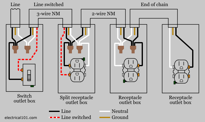
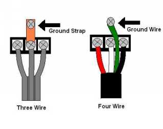
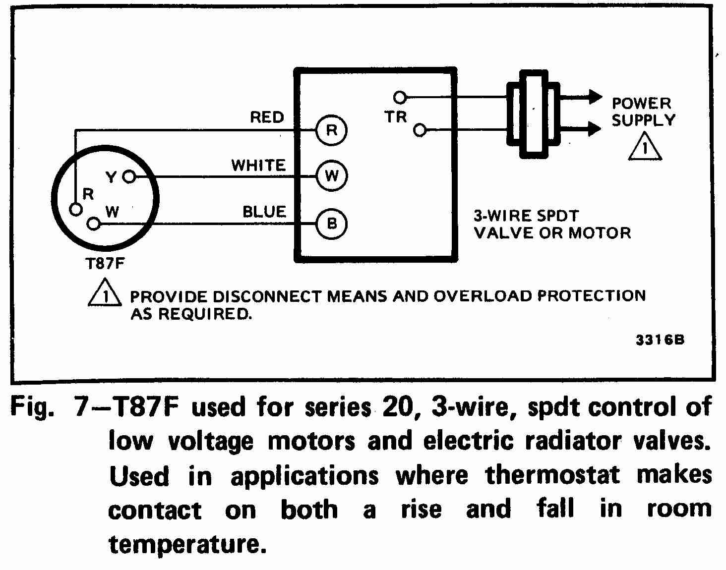
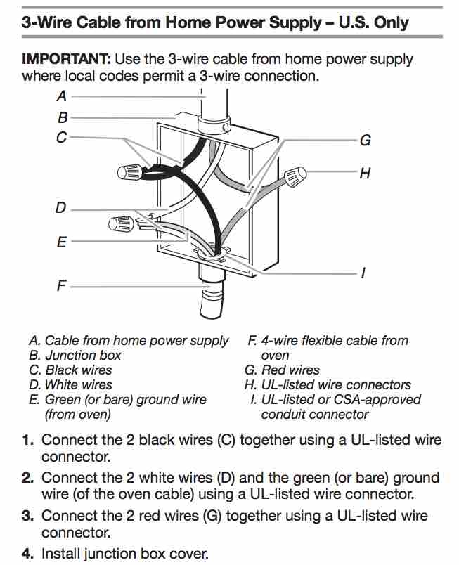
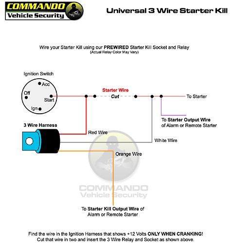
Honestly we also have been noticed that 3 wire 220v wiring diagram is being one of the most popular subject at this moment. These wiring options include.

Submersible Well Pump Wiring Diagrams Lovetoknow
3 wire wiring diagram. It shows the parts of the circuit as streamlined forms and also the power as well as signal links in between the gadgets. Youll generally find the wire gauge marked on the cord sheathing or on the plug. A very first appearance at a circuit diagram might be confusing yet if you can check out a subway map you can read schematics. When replacing a three prong plug connect the black wire in the cord to the brass terminal screw the white wire to the chrome terminal and the green or bare wire which is the ground wire to the green ground screw in the plug. In most cases you will not need to add relays for this type. Three way switch wiring with light middle.
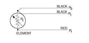
Rtd wiring configurations there are three types of wire configurations 2 wire 3 wire and 4 wire that are commonly used in rtd sensing circuits. Three prong plugs have a hot wire a neutral wire and a ground wire. Most of the newer alarms and keyless entries on the market today have both positive and negative 200 ma door lock outputs that are. Door locks 3 wire positive type a relay wiring diagram. Several transmitter wiring options exist. Twelve gauge cords have larger diameter wires and are suitable for heavier loads such as operating power tools.
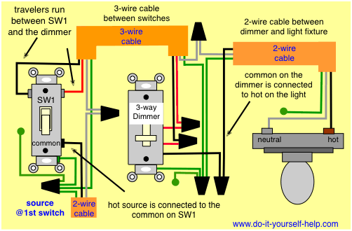
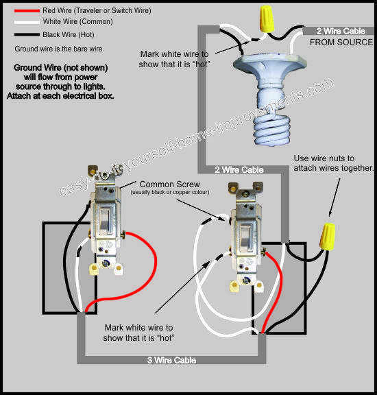
A 14 gauge cord is suitable for indoor appliances and indoor or outdoor lights. This is one of the most common type of door lock switch configurations found in most vehicles. The only wiring diagram shown here that is legal to use is 3 although 1 could be modified by adding a 2 wire cable from the lower box to the light. Three prong extension cords generally come in two wire gauges. 3 way switch wiring with. Getting from factor a to point b.
Three wire alternator wiring diagram a novice s overview of circuit diagrams. Any neutrals in the switch box that are unused are either spliced together or in the case of a single neutral simply capped off with a wire nut and tucked back into the box. Current source transmitter non isolated 3 wire current sink transmitter non isolated 3 wire fully isolated 4 wire two wire loop powered transmitters. The design of the associated control panel dictates which option should be used. The source in this circuit is at the first switch and the light fixture is. The objective is the same.
Literally a circuit is the path that permits electrical power to flow. 3 way switch wiring diagrams wiring diagram 3 way switch with light at the end. 208v single phase and 208v 3 phase oem panels pertaining to 3 wire 220v wiring diagram image size 486 x 342 px and to view image details please click the image. 4 20 ma transmitter wiring. A wiring diagram is a simplified traditional pictorial depiction of an electric circuit. A 2 wire configuration with a compensating loop is also an option.
Collection of three wire alternator wiring diagram. So that we attempted to get some good 3 wire 220v wiring diagram photo to suit your needs. 2 wire rtd connections the 2 wire rtd configuration is the simplest among rtd circuit designs. In this diagram the electrical source is at the first switch and the.


