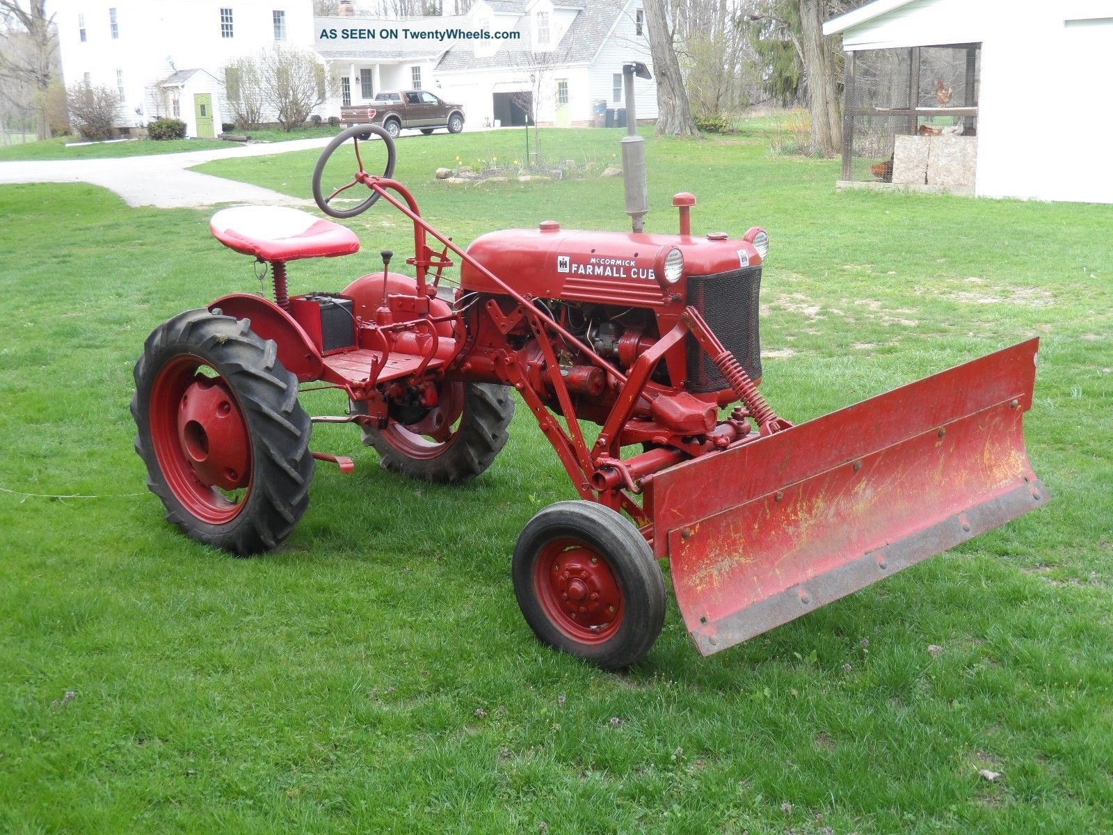
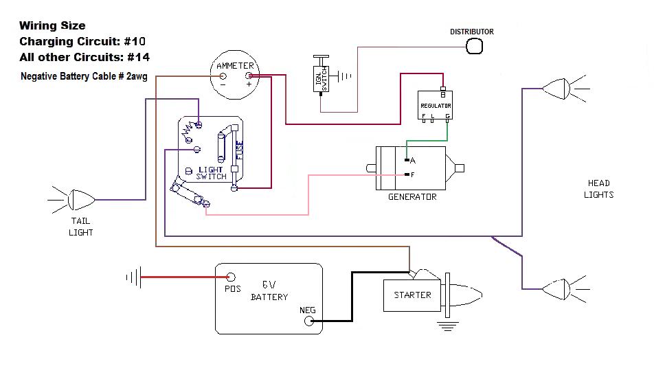
Rubber gasket for 45 light assembly. I am loking for a wiring diagram for a farmall international cub 1949 magneto generator 6v.

1948 Farmall International Tractor Wiring Wiring Diagram
1948 farmall cub wiring diagram. The blue green wire i used 10 gauge wire. Replaces 350 920 r1. Having a 6 volt cub with a mag is not big deal and is very easy to rewire or straighten out the rats nest you have. Cub lo boy 154 wiring diagram collection ford 8n. Farmall cub generators operate on 6 volt systems. Replaces 376 852 r91.
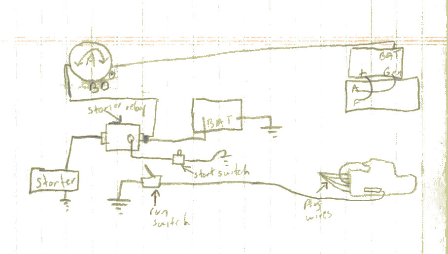
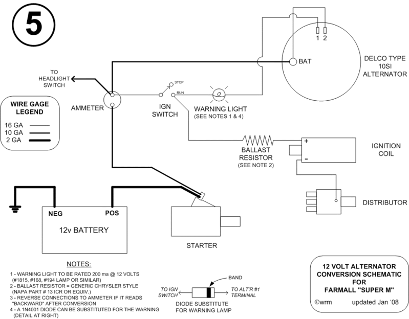
1008034 84 pages electrical wiring diagram included operator manuals explain how to operate the tractor. A wiring diagram is a simplified conventional photographic depiction of an electrical circuit. It shows the components of the circuit as simplified shapes and also the power and also signal connections between the gadgets. Ok im working on wiring now. This book is sometimes referred to as an owners manual and it is a reprint of the original book that came with the tractor. It is a 1948 cub with mag and 3 wire voltage regulator 6 volt positive ground so i wired like this diagram and made a diagram from my old rotted harness and mine had a extra wire from f on gen to f on voltage reg which is this right.
Replaces 350 478 r1. B 1939 1948. Use keywords or part numbers instead of full sentences for best results. 737 3025 1234 filter oil pump etc. As the armature spins power is supplied to the field windings creating an. J4 magneto rotor original ih part.
Cub cub lo boy clamp lamp assembly. My system is 12 v system. The poles in a generator are the two sets of field windings surrounding the inside of the generator. I am looking for a diagram of the magneto distributor for a 1948 farmall cub. A generator must be polarized properly every time the battery is low or disconnected. Also i ran all lights with a 14 gauge wire.
International farmall fits. Farmall cub tractor 147 1253 catalog search note. Farmall cub wiring 1949 with magneto in reply to dan 04 11 2004 182537 dan. Assortment of farmall h 12 volt conversion wiring diagram. Any assistance would be greatly appreciated.
