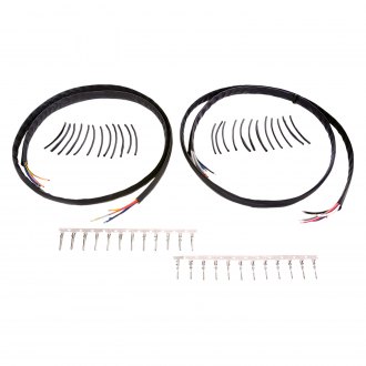
View as grid list. Spyke 420010 universal plug wires.
32 Harley Davidson Starter Diagram Wiring Diagram List
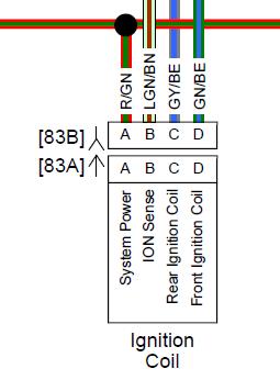
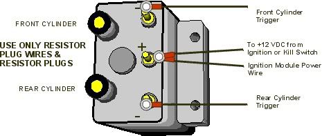
Spyke ignition wiring diagram. Warrants to the original retail purchaser of a spyke ignition that it will free of charge repair or replace at its own option. Df coils can not be wired for 2 plug per cylinder dual fire. Coil wiring 12 vdc from kill switch usually whiteblack plug wires may go to either cylinder use only resistor plug wires resistor plugs super comp dual fire igntions coil wiring black coil trigger wire white to 12 vdc from ignition switch white 12 vdc to module sf coils can not be wired for 2 plugcylinder single fire. Spyke 449010 dual fire coil with 3 ohms resistance for 80 02 big twin harley models except fuel injected. To be defective in material or workmanship. I had to cut into the wiring bundle and separate each wire and test it till i finally found the fault.
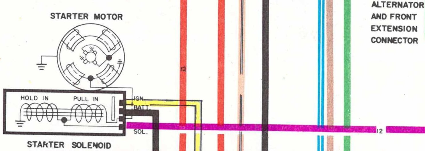
Transmission late 1984 1985 wiring diagram flhs 1980 1981 prestolite starter motor. Spyke 420011 fxr plug wires. Rocker arm and pushrod assembly. All the wires were one color white. See coil wiring diagrams for dual fire or 2 plugcylinder operation. Spyke doesnt support ss rev gear installations.
Limited warranty spyke inc. You are jumping double the gap under compression when dual plugging. Wiring diagram xlch. Wiring diagram coil wiring for distributor mounted single fire ignition 2 plugscylinder 3 ohm dual fire coils important note. I found it hard to believe but it was true. If both plug on same cylinder are gapped at 0040 your jumping 0080 under pressure.
Spyke 449010 dual fire coil with 3 ohms resistance for 80 02 big twin harley models except fuel injected 7144. Kickstarter assembly 1966 1969. Engine so the wire exits in the location you wish the ignition wiring harness to exit and the rotor pins are located as shown in diagram. See wiring diagram do not hook the black. Use only resistor plug wires resistor plugs to 12 vdc from ignition or kill switch usually white with black stripe white 12 vdc wiring diagram red tach trigger tach factory tach wire normally pink voes switch green voes ground if not used voes should be adjusted to 5 5 12 lbs rigger white 12 vdc timing line. Wiring diagram xlh 1970 1971 custom universal basic wiring diagram.
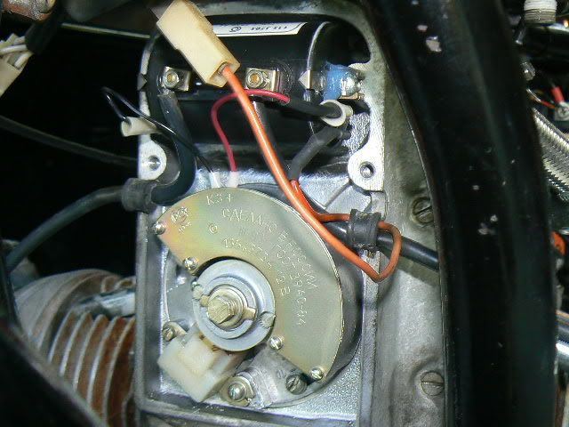
Ignition module or coil. Warrants to the original retail purchaser of a spyke ignition that it will free of charge repair or replace at its own option the product if returned to spyke inc. Insert ignition and lock into place using the. Here are some wiring diagrams so you can see what i mean. Ignition system late 1978 1979 starter solenoid 1970 1980 rocker arm and pushrod assembly. In the example below the wire will exit to the rear inside of the engine.
Seems to me it was a 1965 or 66 model. Within 6 months after purchase and if found by spyke inc. So todays wiring is pretty good. Pull ignition wire through wire hole rock ignition into cone.
