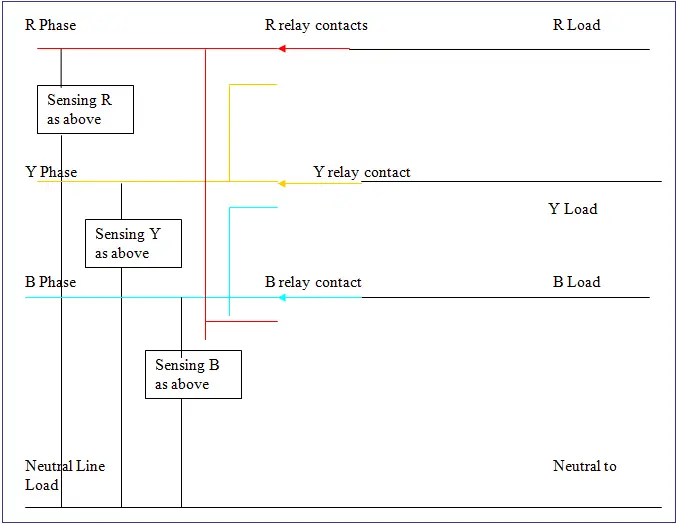
A contactor when closed opens its own auxiliary contact. In fig 2 different connection and wiring diagrams are shown for a two pole single phase manual changeover switch.
20 Luxury Electrical Changeover Switch Wiring Diagram
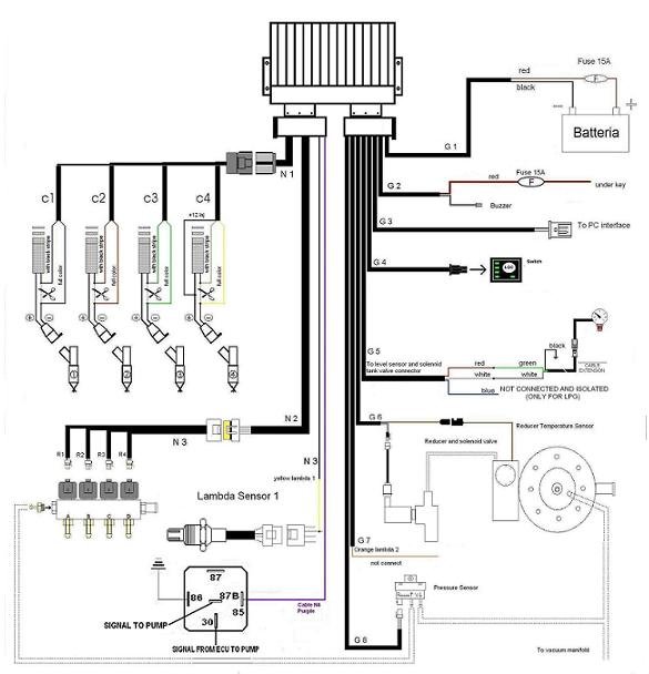
Lpg changeover switch wiring diagram. The upper portion of the changeover switch is directly connected to the main power supply while the lower first and right connections slots are connected to the backup power supply like generator or inverter. Go to the lpg station. Lpg changeover switch wiring diagram nam home pl j2 images stories dok2012 prezentacje prezentacja installation guidelines for the gaseous. No regulations are needed. The change over switch must be mounted using the screws supplied in a visible place easy to reach and to see by the driver. In this automatic changeover switch for generator circuit diagram the contactors of the generator are indicated kg and km.
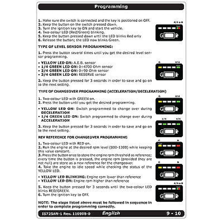
Press and hold the bg button on the switchboard. Turn off the ignition switch while still pressing the bg button. Release the bg button the diodes will. Tech lpg controller installation manual and controller programming manual to perform the lpg level indicator calibration you should fill the lpg tank up following these steps. This post i will shown the complete method of manual or handle change over switch the knob type manual changeover switch wiring same like handle change over switch and its just like a voltmeter sector switch. This contact being in series with the coil of the other contactor will not allow the other contactor to close.
Manual changeover switch are mostly use in 2 types in which one have the move able knob and 2nd one the handle changeover switch. Black brown ignition impulses. Injection as 250 as 250 as 250 working on petrol the change over switch petrol gas change over gas petrol change over level gauge the wire connection is as following. Keep the engine on.


